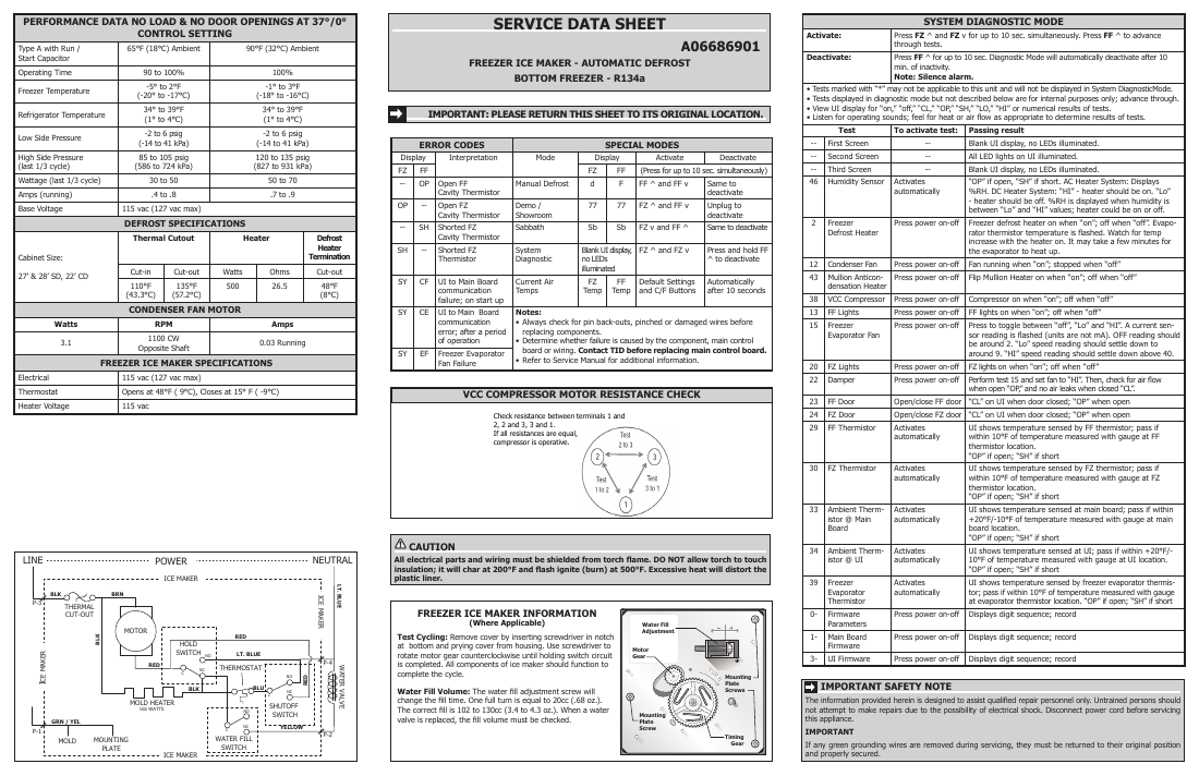
A06686901
| PERFORMANCE DATA NO LOAD & NO DOOR OPENINGS AT 37°/0° CONTROL SETTING | |||||
|---|---|---|---|---|---|
| Type A with Run / Start Capacitor | 65°F (18°C) Ambient | 90°F (32°C) Ambient | |||
| Operating Time | 90 to 100% | 100% | |||
| Freezer Temperature | -5° to 2°F (-20° to -17°C) | -1° to 3°F (-18° to -16°C) | |||
| Refrigerator Temperature | 34° to 39°F (1° to 4°C) | 34° to 39°F (1° to 4°C) | |||
| Low Side Pressure | -2 to 6 psig (-14 to 41 kPa) | -2 to 6 psig (-14 to 41 kPa) | |||
| High Side Pressure (last 1/3 cycle) | 85 to 105 psig (586 to 724 kPa) | 120 to 135 psig (827 to 931 kPa) | |||
| Wattage (last 1/3 cycle) | 30 to 50 | 50 to 70 | |||
| Amps (running) | .4 to .8 | .7 to .9 | |||
| Base Voltage | 115 vac (127 vac max) | ||||
| DEFROST SPECIFICATIONS | |||||
| Cabinet Size: 27' & 28' SD, 22' CD | Thermal Cutout Check at the connector from harness into the inverter the machine | board, compartment. | Heater → the power cord located in | yes | Defrost Heater Termination Check at Inverter Compressor (BLK and RED |
| Cut-in (PUR and WHT Is Inverter | Cut-out wires) Board receiving | Watts 115 VAC | Ohms | Cut-out Is Inverter Board VAC 1-5 | |
| 110°F (43.3°C) from power | 135°F (57.2°C) supply? no | 500 | 26.5 | 48°F (8°C) and Control Board? | |
| CONDENSER FAN MOTOR no | |||||
| Watts | RPM | Amps | |||
| 3.1 | 1100 CW Opposite Shaft • Check voltage supply. • Check and repair | 0.03 Running power | |||
| FREEZER ICE MAKER SPECIFICATIONS → Check at Main cord harness wiring and connections. | |||||
| Electrical | 115 vac (127 vac max) Is Main Control | ||||
| Thermostat | Opens at 48°F ( 9°C), Closes at 15° F ( -9°C) 10-15 VAC and Inverter Board? | ||||
| Heater Voltage | 115 vac yes |
Table Caption: This table provides performance data for a refrigerator, including operating conditions, temperature ranges, pressure readings, electrical specifications, and defrost and fan motor details. It also outlines the specifications for the freezer ice maker, including thermostat and heater voltage.
A06686901
FREEZER ICE MAKER - AUTOMATIC DEFROST
BOTTOM FREEZER - R134a
IMPORTANT: PLEASE RETURN THIS SHEET TO ITS ORIGINAL LOCATION.
Check at Inverter Board on
Is Inverter Board receiving 10-15
VAC and 1-5 VDC from Main
Check at Main Control Board
(BLK/WHT and RED/BLK wires)
| ERROR CODES | SPECIAL MODES | ||||||
|---|---|---|---|---|---|---|---|
| Display | Interpretation | Mode | Display | Activate | Deactivate | ||
| FZ | FF | FZ | FF | (Press for up to 10 sec. simultaneously) | |||
| -- | OP | Open FF Cavity Thermistor | Manual Defrost | d | F | FF ^ and FF v | Same to deactivate |
| OP | -- | Open FZ Cavity Thermistor | Demo / Showroom | 77 | 77 | FZ ^ and FF v | Unplug to deactivate |
| -- | SH | Shorted FZ Cavity Thermistor → Remove inverter | Sabbath box from the | Sb → | Sb Check connections | FZ v and FF ^ from Inverter | Same to deactivate |
| SH 10-15 | -- yes | Shorted FZ Thermistor compressor and across compressor shown. | System Diagnostic check resistance winding pairs as | Blank UI display no LEDs illuminated Board to Are connections yes | Board to | , FZ ^ and FZ v Compressor from Compressor intact? | Press and hold FF ^ to deactivate Inverter |
| SY | CF | UI to Main Board communication failure; on start up Is resistance across pairs equal? no | Current Air Temps all winding | FZ Temp | FF Temp | Default Settings and C/F Buttons | Automatically after 10 seconds |
| SY | CE | UI to Main Board communication error; after a period of operation Replace Inverter Board. | Notes: • Always check for pin back-outs, pinched or damaged wires before replacing components. • Determine whether failure is caused by the component, main control Compressor and Identify and repair damaged wires or poor connections no | ||||
| SY | EF | Freezer Evaporator Fan Failure | board or wiring. Contact TID before replacing main control board. • Refer to Service Manual for additional information. between Inverter Board and Compressor. yes |
Table Caption: This table outlines error codes and special modes for a refrigerator or freezer system, detailing their display indicators, interpretations, and activation/deactivation procedures.
Is Main Control Board sending
10-15 VAC and 1-5 VDC to
Identify and repair damaged wires or poor connections between Main Control
Board and Inverter Board.
Replace Main Control Board.
CAUTION
All electrical parts and wiring must be shielded from torch flame. DO NOT allow torch to touch insulation; it will char at 200°F and flash ignite (burn) at 500°F. Excessive heat will distort the plastic liner.
FREEZER ICE MAKER INFORMATION (Where Applicable)
Test Cycling: Remove cover by inserting screwdriver in notch at bottom and prying cover from housing. Use screwdriver to rotate motor gear counterclockwise until holding switch circuit is completed. All components of ice maker should function to complete the cycle.
Water Fill Volume: The water fill adjustment screw will change the fill time. One full turn is equal to 20cc (.68 oz.). The correct fill is 102 to 130cc (3.4 to 4.3 oz.). When a water valve is replaced, the
