Giriş
Printed parts needed:
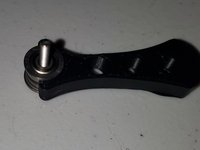
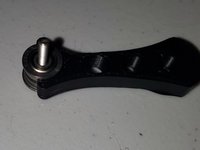
1x Bearing tool
Neye ihtiyacın var
-
-
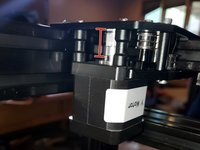
In a CoreXY setup both X and Y stepper move together. Technically the top left stepper is the X and the top right stepper is the Y
-
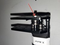
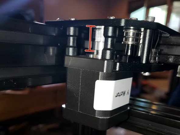
Start with taking your X motor and slide the timing gear on to the stepper shaft making sure the set/grub screw when tightened will be on the flat side of the stepper shaft.
-
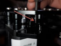
Note the timing gear orientation. We will need to make height adjustments after the belts are on
-
Tighten the grub screw
-
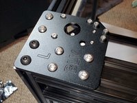
Slide in 3x M3x35mm socket head screws and 3x 29.2mm motor standoffs. Note the front stepper mounting hole that is too large for a M3
-
Thread in the 3x M3x35mm screws into the stepper but not tight. Note the orientation of the stepper. I noticed this after I assembled this part but the wire plug should towards the middle of the printer. I had to rotate it 90 clockwise from the picture
-
-
-
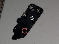
Take 2x M3x30mm socket head screws and slide them into the bearing guide holes and a M3x10mm socket head cap screw for the stepper mount. Left Corner Bottom Bracket. Slide a F623zz bearing so the lip is towards the bracket. Next a M3 washer. Finally another F623zz where the lip is away from the bracket.
-
Assembly the Top Left corner to the Bottom Left corner by threading the M3x30 screws into the top bracket. Tighten the screws enough so the bearings won't fall out, do not tighten them all the way
-
-
-
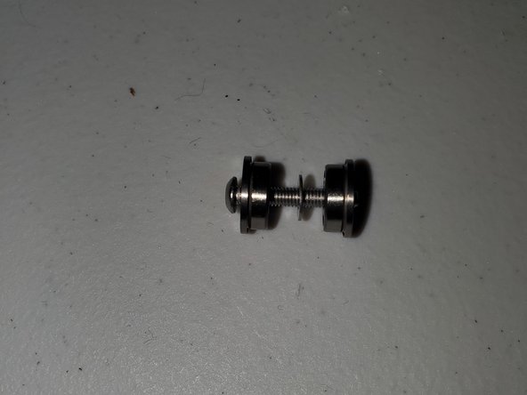
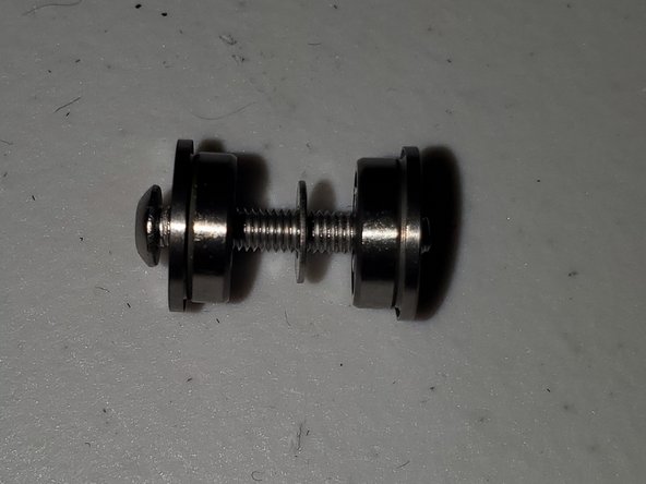
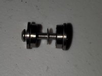
Take 1x M3x20mm screw. Slide 2 F623zz bearings with a M3 washer in the middle.
-
Push the bearings together and insert the washer bearing sandwich into the bearing tool and remove the M3 screw
-
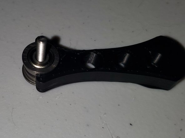
Insert the bearing sandwich with the bearing tool into the Left Rear Corner assembly using a 1x M3x30mm socket head screw but do not tighten completely.
-
-
-
-
Insert 2x M3x30 socket head Cap screws with 2x 20mm standoffs. Do not tighten the screws completely
-
-
-
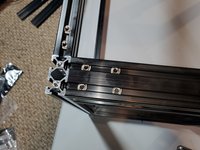
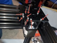
Drop 6x M5 T-nuts into the frame channel at the back top left.
-
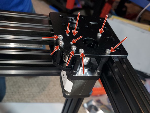
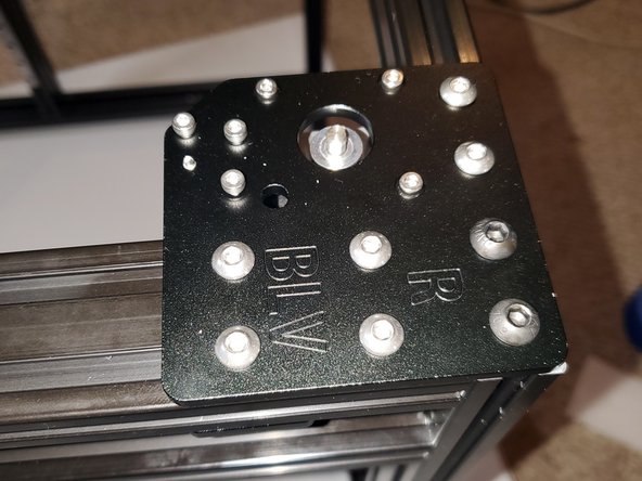
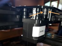
Make sure these 9 screws are not completely tight. In reality you only need to tighten them enough so the screws can grab the threads and not fall out.
-
Place the Left Corner assembly on to the back top left corner of the frame
-
Thread in 2x M6x10 button head screws into the 2040 first. Tighten them until they're snug than back off 1/4 turn. We do this in case we need to adjust the alignment of the top plate
-
Thread in 6x M5x8 button head screws into the T-nuts in the frame channel until they are snug. Loosen them 1/4 turn
-
-
-
This was the hardest part for me because I didn't flip the frame.
-
Turn the frame upside down so the top is now the bottom.
-
Insert 4x M5 T-nuts into the frame channel and slide them so you can thread 4x M5x8 button head screws into them. Again tighten the screws snug than loosen 1/4 turn.
-
Turn the frame over and tighten the 2x M6 button head screws than the 6x M5x8 button head screws to secure the top plate to the frame.
-
Tighten the 4 stepper mounting bolts. Do not forget about the M3x10
-
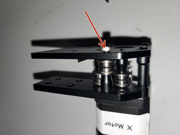
Tighten the M3 screws for the bearings. 1 on top and 2 on the bottom of the assembly.
-
Tighten the 2x M3 screws for the standoff spacers
-
Tighten the 4x M5x8 button head screws on the bottom plate
-
-
-
In a CoreXY setup both X and Y stepper move together. Technically the top left stepper is the X and the top right stepper is the Y
-
The right corner is assembled in virtually the same manner as the left. However I tried doing it in the same manner as the videos posted on the project page
-
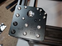
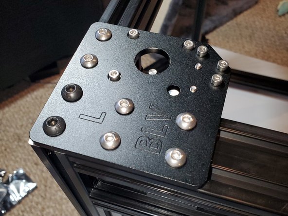
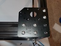
Attach the top plate to the frame with 2x M6x10mm button head screws, 6x M5 T-nuts and 6x M5x8mm button head screws. Tighten the screws completely.
-
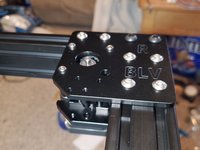
Insert 3x M3x25mm socket head screws into the stepper mounts. Slide 3x 19mm standoffs over the screws than thread the M3x25mm into the stepper motor but do not tighten.
-
The plug on the stepper motor should be facing towards the X motor
-
-
-
Insert 4x M5x8mm button head screw into the bottom plate and thread on 4x M5 T-nuts enough so the threads will grab.
-
Insert 1x M3x30mm socket head screw into the bottom plate.
-
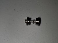
Take 1x M3x20mm screw. Slide 2 F623zz bearings with a M3 washer in the middle.
-
Push the bearings together and insert the washer bearing sandwich into the bearing tool and remove the M3 screw
-
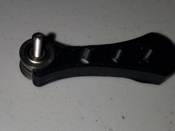
Insert the bearing sandwich with the bearing tool over the M3x30mm socket head screw
-
-
-
Thread in the M3x30 with bearings on it into the top plate to prevent the bearing from falling out.
-
Position the bottom plate so 4x M5x8 button head screws so the T-nuts will drop into the channel. Do not tighten completely.
-
Using a M3x6 socket head screw attach the bottom plate to the stepper but do not tighten.
-
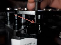
Insert 2 bearing sandwiches (bearing+washer+bearing) with the bearing tool into the assembly and thread in 2x M3x30 socket head screws
-
Insert 1x 19mm standoff spacer and thread in a m3x30mm socket head screw. Do not tighten
-
Tighten the 4x stepper screws.
-
Tighten the bearing screws. 2x on top and 1x on the bottom. Tighten the standoff spacer screw
-
Tighten the 4x M5x8mm button head screws on the bottom plate
-


I wasn’t paid to write these guides. Ben asked me to do it as a favor to him. Considering all that he’s done for our community I felt it was the least I could do. To be honest even though it took about 2 months to build and document, I had a lot of fun doing it. It forced me to write guides in a manner that was easy for everyone to understand and cleanup my Github so I could share any files that were used that aren’t part of the original download. You’re not obligated but if you would like, feel free to donate.
I wasn’t paid to write these guides. Ben asked me to do it as a favor to him. Considering all that he’s done for our community I felt it was the least I could do. To be honest even though it took about 2 months to build and document, I had a lot of fun doing it. It forced me to write guides in a manner that was easy for everyone to understand and cleanup my Github so I could share any files that were used that aren’t part of the original download. You’re not obligated but if you would like, feel free to donate.
İptal et: Bu kılavuzu tamamlamadım.
9 farklı kişi bu kılavuzu tamamladı.