Bu sürüm, hatalı düzenlemeler içerebilir. En son doğrulanmış bellek kopyası dönün.
Neye ihtiyacın var
-
Bu adım çevrilmemiş. Çevrilmesine yardım edin
-
Remove 2 screws, one each side, securing the top cover.
-
-
Bu adım çevrilmemiş. Çevrilmesine yardım edin
-
Release the top cover with a spudger inserted along the front edge. Lift it off from the front.
-
-
Bu adım çevrilmemiş. Çevrilmesine yardım edin
-
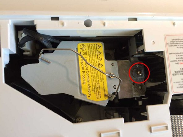
Remove the transparent film over the lamp, and put it aside.
-
Lift the lamp handle. Undo the captive screw which secures the lamp. Disconnect the lamp power connector and lift out the lamp.
-
-
Bu adım çevrilmemiş. Çevrilmesine yardım edin
-
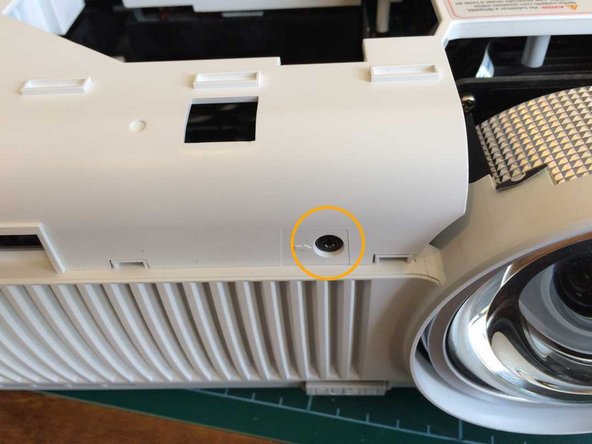
Remove a screw from just in front of the control buttons.
-
Remove a screw from the front just to the left of the lens.
-
Turn the projector over and remove 5 recessed screws from the holes with arrows against them.
-
-
Bu adım çevrilmemiş. Çevrilmesine yardım edin
-
Release the top cover by running a spudger around all 4 sides. Remove the cover.
-
-
-
Bu adım çevrilmemiş. Çevrilmesine yardım edin
-
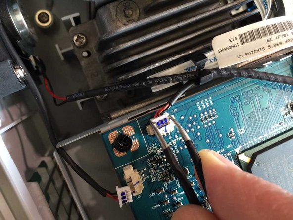
Disconnect 6 connectors. Do not pull them out by the wires as the wires may come out of the plugs. Instead, ease them out with a pair of tweezers as shown, or with a thumbnail on each side.
-
Gently pull the ribbon cable out of its socket.
-
-
Bu adım çevrilmemiş. Çevrilmesine yardım edin
-
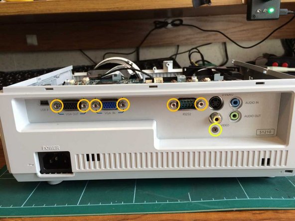
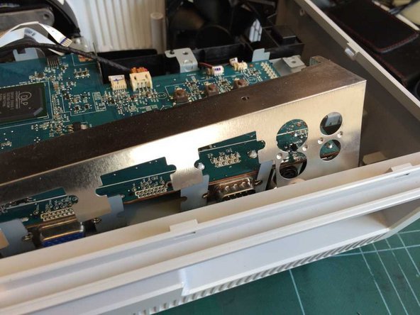
Remove 4 screws securing the main board.
-
Remove 6 binding posts on the VGA and serial sockets with a 3/16in or 5mm socket or spanner, a small adjustable spanner, or if you have none of those, a pair of pliers.
-
Remove a screw from below the phono video socket.
-
Angle the rear panel backwards in order to remove it. Remove also the metal screen.
-
-
Bu adım çevrilmemiş. Çevrilmesine yardım edin
-
Gently lift the main board off the optical assembly and power supply connectors, and put it aside.
-
-
Bu adım çevrilmemiş. Çevrilmesine yardım edin
-
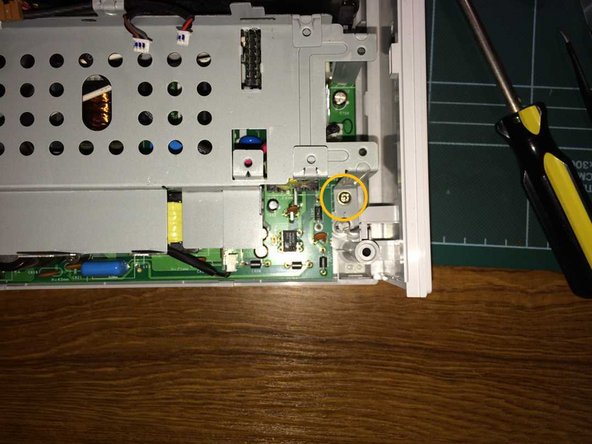
A long magnetic screwdriver is very helpful for this step, and almost essential for reassembly.
-
Remove a screw and toothed lock washer from the rear left of the metal plate.
-
Remove a screw from the rear right of the metal plate.
-
Remove a screw from the front right of the metal plate.
-
-
Bu adım çevrilmemiş. Çevrilmesine yardım edin
-
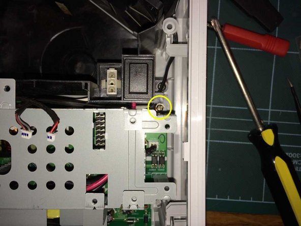
Remove a black screw from the front of the metal plate engaging with the optical assembly. This may be hidden by the wires passing through the adjacent wire clip.
-
Lift out the metal plate.
-
-
Bu adım çevrilmemiş. Çevrilmesine yardım edin
-
Remove the front panel by releasing 3 clips along the bottom, using a spudger, then angling it forwards.
-
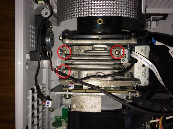
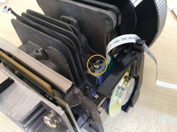
Remove 3 screws on the top of the optical assembly. On the right, do not remove the adjacent screw securing the colour wheel assembly.
-
Lift out the complete optical assembly.
-
-
Bu adım çevrilmemiş. Çevrilmesine yardım edin
-
Remove 2 screws on the side of the colour wheel guard and remove the guard.
-
Remove a screw above and behind the colour wheel, and remove the wheel assembly.
-
-
Bu adım çevrilmemiş. Çevrilmesine yardım edin
-
Disconnect the rotary position sensor cable.
-
Remove 2 small screws and remove the black plastic piece.
-
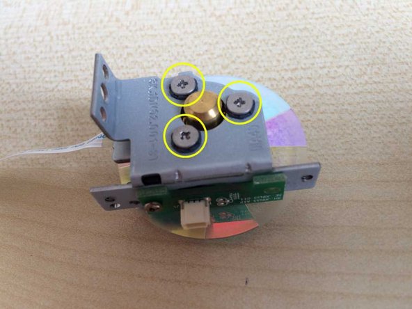
Remove 3 screws and lift them out of their rubber grommets.
-
Holding it by the ribbon cable, rotate the bare colour wheel through 90 degrees in order to remove it.
-
No further disassembly is feasible, and the bearing is not accessible for lubrication. Flicking the edge with a finger, the wheel should spin completely freely.
-


Ekip
