Giriş
My machine would not turn on any more (you'd press the button and nothing happens). So I decided to take a look inside.
Turns out the PCB is broken. If you can get a replacement, that's easy, but otherwise I show you another idea how to fix it here.
IMPORTANT NOTE: you only need to open the bottom compartment for this!
Neye ihtiyacın var
-
-
Always start by unplugging your device and wait until it is fully cooled down (the temperature reading is analogue, so you can use it as an indication)
-
Then remove the water compartment. Place it far from where you are working on the device.
-
The device is sectioned into three general compartments:
-
Bottom compartment (easiest to access): contains a simple controller board that allows you to turn the device on/off with a toggle button and turns it off automatically after a prolonged period of misuse.
-
Middle compartment (hardest to access): contains the cabling, the pump, and a valve.
-
Top compartment: contains the heating block with heat switches and fuse, the levers, the indicator lamps, and some water tubing.
-
For the PCB replacement, you only need to access the bottom compartment!
-
-
-
Pretty straight forward to access. You'll need to find a good surface to place the device sideways without damaging the levers (or the thermometer).
-
The use of a piece of foam, or ugly pillow might be handy.
-
Use a regular Phillips (+) screwdriver to remove the six screws at the bottom of the device. Note that the one in the centre front is shorter than the others. Make sure it goes back in the right spot!
-
Remove the bottom plate. You'll find a PCB and some cabling, that's it.
-
-
-
-
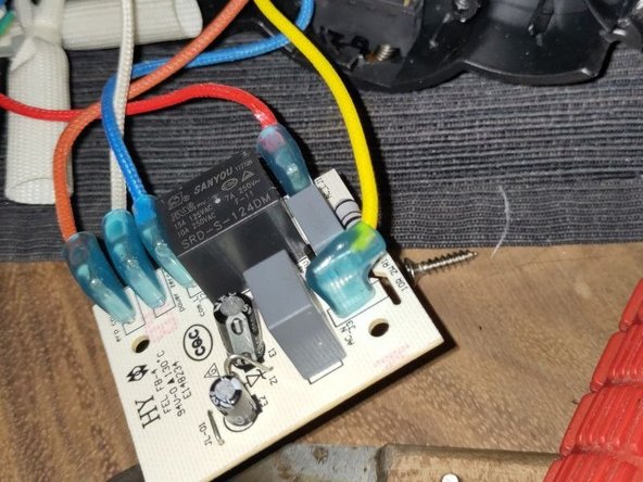
After removing the bottom plate, you can remove the PCB with just two screws. To remove the connectors, using a set of pliers can be useful.
-
In my case, this PCB was broken. At first I thought the Sanyou SRD-S-124DM relay was broken, but after some more investigation, I found that the board was not producing DC voltage any more.
-
For now I've given up fixing the PCB and could not find a replacement yet, but I found another "quick" fix, see next steps.
-
If you find a replacement PCB, just plug all the plugs back in the right place and replace the two screws. Don't forget to replace the sheet of plastic as well.
-
-
-
The PCB has a very simple functionality: if you press the toggle button, it turns on a relay to power the device. If you press the toggle button again, it will turn that relay off again, powering down the entire device.
-
It also checks if the pump ever gets turned on (which means you are either tapping hot water or preparing a coffee). If you don't do that for a while, it will also turn off the machine.
-
The first part, we can also easily do with a switch. It works again then, but if I forget to turn it off, it will stay on forever, eating a lot of electricity!
-
The switch used in the device just sends a short pulse to the PCB (toggle). If you want to remove the PCB, you'll need to replace this with a switch that remains switched on until you turn it off again.
-
CAUTION: if you follow my instructions, you are messing with main voltage circuits! This can be dangerous! So only continue if you understand what I've written above and you know what you are doing!
-
-
-
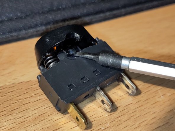
Remove all cables from the switch. There is a small clip, that makes it easier to remove if you press it.
-
Be careful when removing the switch (if you ever want to put it back):
-
Carefully lift one of the latches with a flathead screwdriver to pop the cap off
-
Take out the switch from the inside
-
After replacing the spring, you can put it together again to make sure you don't lose any parts.
-
If you want to put it back later, pop the cap off with the same trick and put it back into the device (don't forget the spring and make sure you get the right orientation).
-
-
-
I used a regular switch (that even fit the hole of the old switch). It needs to connect the red (AC_L) and blue (COM_L) when switched on.
-
I then taped the orange (erp count) and yellow (AC_N) cables ends, so they could not make accidental contact.
-
I removed the PCB.
-
I also removed the white cable between the old switch and the PCB (pwr zero).
-
Put the bottom lid back and replace the six screws (making sure to put the shorter one in the right place).
-


Please remember to turn off the device after use!
Please remember to turn off the device after use!