Bu sürüm, hatalı düzenlemeler içerebilir. En son doğrulanmış bellek kopyası dönün.
Neye ihtiyacın var
-
Bu adım çevrilmemiş. Çevrilmesine yardım edin
-
Remove the wrist strap, if present.
-
Remove the lithium-ion battery.
-
-
Bu adım çevrilmemiş. Çevrilmesine yardım edin
-
Remove the two 4 mm Phillips #00 screws on the bottom of the camera.
-
Remove the screw next to the wrist strap attachment.
-
Pull up the “A/V OUT DIGITAL” cover and remove the screw above the USB port.
-
-
Bu adım çevrilmemiş. Çevrilmesine yardım edin
-
Carefully unhook the “A/V OUT DIGITAL” cover from the hinge.
-
-
Bu adım çevrilmemiş. Çevrilmesine yardım edin
-
Pull the front cover from the camera by using gentle upward pressure.
-
-
Bu adım çevrilmemiş. Çevrilmesine yardım edin
-
Remove the two Phillips #00 screws from the flat end of the camera.
-
Remove the black L-shaped side cover plate.
-
Remove the silver u-shaped retainer plate.
-
-
-
Bu adım çevrilmemiş. Çevrilmesine yardım edin
-
The first screw that needs to be removed is located on the bottom of the camera, on the left hand side.
-
Using a Phillips #00 screwdriver remove the 0.133in silver screw on the bottom left-hand side.
-
-
Bu adım çevrilmemiş. Çevrilmesine yardım edin
-
The second screw that needs to be removed is located on the top of the camera.
-
Using the same Phillips head screwdriver, remove the last 0.133in silver screw.
-
This will detach a silver U-shaped piece that was holding LCD screen on. Remove the piece and put it to the side.
-
-
Bu adım çevrilmemiş. Çevrilmesine yardım edin
-
The LCD screen should now only be attached by the LCD data cable.
-
Lift the screen from the right side and use a small screwdriver or other small opening device to flip the black portion of the connector upward to unlock it.
-
Carefully slide the data cable out of the connector.
-
The LCD should still be connected by the backlight cable.
-
-
Bu adım çevrilmemiş. Çevrilmesine yardım edin
-
To remove the backlight cable, use another small opening device to unlock the backlight cable.
-
Carefully slide out the backlight cable.
-
The LCD screen should now be fully detached from the camera body.
-
-
Bu adım çevrilmemiş. Çevrilmesine yardım edin
-
The LCD screen casing is connected by 4 claws located on the top and bottom on the left and right hand side.
-
Carefully disengage the claws by gently prying them off one by one.
-
Once the claws are disengaged, the back of the casing will still be connected to the front casing by the backlight cable.
-
Carefully peel the backlight cable off of the casing.
-
-
Bu adım çevrilmemiş. Çevrilmesine yardım edin
-
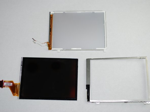
The LCD screen and housing should now be in three pieces:
-
LCD screen
-
LCD screen frame
-
LCD screen back housing
-
The LCD screen itself can now be removed and fixed/replaced.
-
-
Bu adım çevrilmemiş. Çevrilmesine yardım edin
-
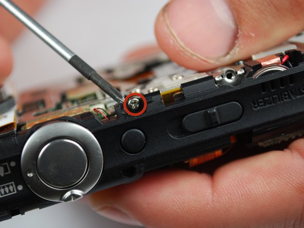
With the case and LCD screen removed, you are ready to remove the release button.
-
Begin by using the Philips #00 screwdriver to remove two silver 0.159in screws on the top and front of the camera.
-
-
Bu adım çevrilmemiş. Çevrilmesine yardım edin
-
The top plastic piece holding the release button should be held on only by a red-and-black wire connector to the logic board.
-
Remove the connector from the logic board and detach the release button housing from the camera.
-
-
Bu adım çevrilmemiş. Çevrilmesine yardım edin
-
With the plastic housing for the release button removed from the camera, use the Philips #00 screwdriver to remove two silver 0.090in screws.
-
The release button can now be removed and fixed or replaced.
-
-
Bu adım çevrilmemiş. Çevrilmesine yardım edin
-
Begin by removing two silver 0.080in screw on the left side of the camera.
-
-
Bu adım çevrilmemiş. Çevrilmesine yardım edin
-
With the case, LCD screen, and release button housing removed, the broken flash unit can be removed and replaced.
-
Begin by disconnecting the hanging flash/speaker unit from the connector on top of the camera.
-
-
Bu adım çevrilmemiş. Çevrilmesine yardım edin
-
Next, gently disconnect the plastic piece on top of the flash/speaker wiring by prying open the claws on either side.
-
The flash unit can now be removed and replaced.
-


Ekip

Cal Poly, Team 10-45, Garner Spring 2010 Cal Poly, Team 10-45, Garner Spring 2010 üyesi
CPSU-GARNER-S10S10G45
4 Üyeler
6 adet Kılavuz yazıldı