Ana içeriğe geç

Disassembling Canon Powershot SD880 Logic Board

Neye ihtiyacın var

  1. Disassembling Canon Powershot SD880 Logic Board, Back Cover: adım 1, 3 resimden 1. Disassembling Canon Powershot SD880 Logic Board, Back Cover: adım 1, 3 resimden 2. Disassembling Canon Powershot SD880 Logic Board, Back Cover: adım 1, 3 resimden 3.
    • Remove the two 2.4 mm screws on the side of the camera that are next to the LCD screen using a Phillips #00 screwdriver.

    • Remove the two 4.1 mm screws on the other side using a Phillips #00 screwdriver.

    • One screw will be located under the rubber USB flap.

    • Remove the single 2.6 mm screw from the bottom of the camera using a Phillips #00 screwdriver.

    • Slowly pull the back cover off of the camera.

  2. Disassembling Canon Powershot SD880 Logic Board, Front Cover: adım 2, 3 resimden 1. Disassembling Canon Powershot SD880 Logic Board, Front Cover: adım 2, 3 resimden 2. Disassembling Canon Powershot SD880 Logic Board, Front Cover: adım 2, 3 resimden 3.
    • Remove the 2.6 mm screw from the bottom of the camera using a Phillips #00 screwdriver.

    • Remove the 4.1 mm screw from the menu button side of the camera using a Phillips #00 screwdriver.

    • The two screws on the other side of the camera were already removed when the back cover was taken off.

  3. Disassembling Canon Powershot SD880 Logic Board, Top Panel: adım 3, 2 resimden 1. Disassembling Canon Powershot SD880 Logic Board, Top Panel: adım 3, 2 resimden 2.
    • Unplug the green and white plugs that connect the top panel to the top of the logic board.

    • Dislodge the tab above the lens.

    • Dislodge the tab at the back.

  4. Disassembling Canon Powershot SD880 Logic Board, Logic Board: adım 4, 1 resimden 1.
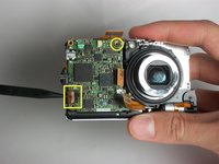
    • Remove 2 screws(1.75mm) using a screwdriver.

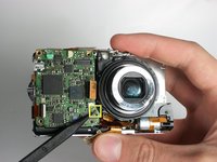
    • Detach 3 ribbons by pulling up on them. All are on the front of the camera.

  5. Disassembling Canon Powershot SD880 Logic Board: adım 5, 2 resimden 1. Disassembling Canon Powershot SD880 Logic Board: adım 5, 2 resimden 2.
    • Remove the newly exposed screw(1.75mm) with screwdriver.

    • Unhinge the black tab to slide out the ribbon.

    • The only thing keeping logic board in place is a black nub. Lift the logic board from that corner with increasing force until it pops out.

Sonuç

To reassemble your device, follow these instructions in reverse order.

Juan Miguel

Üyelik tarihi: 01/13/11

101 İtibar

1 Kılavuz yazıldı

Ekip

Cal Poly, Team 13-3, Forte Winter 2011 Cal Poly, Team 13-3, Forte Winter 2011 üyesi

CPSU-FORTE-W11S13G3

5 Üyeler

8 adet Kılavuz yazıldı

0 Yorum

Yorum Ekle

İstatistikleri Görüntüle:

Son 24 Saat: 0

Son 7 gün: 0

Son 30 gün: 2

Her zaman: 1,981