Bu sürüm, hatalı düzenlemeler içerebilir. En son doğrulanmış bellek kopyası dönün.
Neye ihtiyacın var
-
Bu adım çevrilmemiş. Çevrilmesine yardım edin
-
Heat an iOpener and apply it to the bottom of the phone for one minute.
-
-
Bu adım çevrilmemiş. Çevrilmesine yardım edin
-
Apply a suction cup to the heated bottom edge of the back cover.
-
Lift on the suction cup with strong, steady force to create a gap.
-
Insert an opening pick into the gap.
-
-
Bu adım çevrilmemiş. Çevrilmesine yardım edin
-
Slice the adhesive along the bottom edge of the phone and around the right corner.
-
Leave a pick in the bottom edge to prevent the adhesive from re-sealing.
-
-
Bu adım çevrilmemiş. Çevrilmesine yardım edin
-
Heat the right edge with an iOpener and continue slicing the adhesive with an opening pick.
-
-
Bu adım çevrilmemiş. Çevrilmesine yardım edin
-
Continue heating and slicing through the rest of the phone perimeter. Leave a pick in each edge to prevent the adhesive from resealing.
-
-
Bu adım çevrilmemiş. Çevrilmesine yardım edin
-
Once you have sliced around the perimeter of the phone, carefully lift the left edge of the back cover.
-
Flip the back cover along its long axis and rest it so that the fingerprint sensor cable is not strained.
-
-
Bu adım çevrilmemiş. Çevrilmesine yardım edin
-
Remove the two 4.1 mm-long Phillips screws securing the fingerprint connector bracket.
-
-
Bu adım çevrilmemiş. Çevrilmesine yardım edin
-
Use the point of a spudger to slide the fingerprint connector bracket out from under the NFC coil.
-
Remove the fingerprint connector bracket.
-
-
Bu adım çevrilmemiş. Çevrilmesine yardım edin
-
Use the point of a spudger to pry up and disconnect the fingerprint connector from its socket.
-
-
Bu adım çevrilmemiş. Çevrilmesine yardım edin
-
Remove the five Phillips screws securing the wireless charging coil:
-
Two 1.9 mm screws
-
Two 4.2 mm screws
-
One 4.3 mm screw
-
-
Bu adım çevrilmemiş. Çevrilmesine yardım edin
-
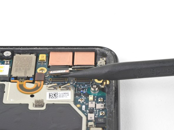
Use the point of a spudger to pry up and disconnect the battery press connector from its socket near the right edge of the phone.
-
-
-
Bu adım çevrilmemiş. Çevrilmesine yardım edin
-
Remove the two screws securing the camera bracket:
-
One 4.1 mm Phillips screw
-
One 4 mm standoff screw
-
Remove the camera bracket.
-
-
Bu adım çevrilmemiş. Çevrilmesine yardım edin
-
Use the point of a spudger to pry up and disconnect the connector for the camera(s) you are replacing.
-
-
Bu adım çevrilmemiş. Çevrilmesine yardım edin
-
Insert the point of a spudger behind the edge of the camera module and pry up to loosen it from the frame.
-
-
Bu adım çevrilmemiş. Çevrilmesine yardım edin
-
Use a pair of blunt nose tweezers to remove the camera(s).
-
-
Bu adım çevrilmemiş. Çevrilmesine yardım edin
-
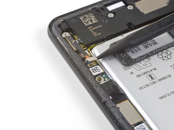
Use the point of a spudger to pry up and disconnect the loudspeaker connector from its motherboard socket near the right edge of the phone.
-
-
Bu adım çevrilmemiş. Çevrilmesine yardım edin
-
Remove the following four Phillips screws:
-
One 1.9 mm screw
-
One 4.3 mm screw
-
Two 4.3 mm screws with thinner shanks
-
Remove the tiny grounding clip from the left screw hole. Be careful not to lose it.
-
Remove the small plastic insert from the right side of the USB-C port.
-
-
Bu adım çevrilmemiş. Çevrilmesine yardım edin
-
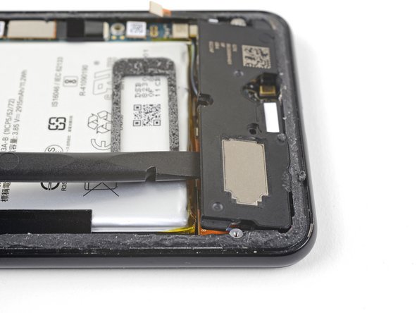
Insert the point of a spudger under the bottom right corner of the loudspeaker.
-
Pry up to loosen the loudspeaker from the phone.
-
-
Bu adım çevrilmemiş. Çevrilmesine yardım edin
-
Insert the point of a spudger under the top left corner of the loudspeaker.
-
Pry up to loosen the loudspeaker.
-
-
Bu adım çevrilmemiş. Çevrilmesine yardım edin
-
Insert the flat end of the spudger under the top edge of the loudspeaker, towards the left edge.
-
Pry up to loosen the loudspeaker.
-
-
Bu adım çevrilmemiş. Çevrilmesine yardım edin
-
Remove the loudspeaker.
-
If it is in good condition, you can re-use the gasket. Make sure that the gasket does not cover the exit hole.
-
If the gasket is pulled out of place, remove it and replace the adhesive with a pre-cut strip or Tesa tape.
-
-
Bu adım çevrilmemiş. Çevrilmesine yardım edin
-
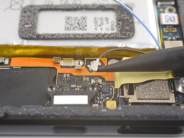
Use the point of a spudger to pry up and disconnect the blue antenna cable from its socket on the charging assembly.
-
-
Bu adım çevrilmemiş. Çevrilmesine yardım edin
-
Use the point of a spudger to carefully pry up and release the blue antenna cable from its grounding clips.
-
-
Bu adım çevrilmemiş. Çevrilmesine yardım edin
-
Use the point of a spudger to pry up and disconnect the black antenna cable from its socket near the USB-C port.
-
-
Bu adım çevrilmemiş. Çevrilmesine yardım edin
-
Carefully de-route both antenna cables and move them away from the charging assembly.
-
-
Bu adım çevrilmemiş. Çevrilmesine yardım edin
-
Use the point of a spudger to pry up and disconnect the charging assembly's connector from its motherboard socket, near the right edge of the phone.
-
Carefully peel the flex cable from the top of the SIM card reader.
-
-
Bu adım çevrilmemiş. Çevrilmesine yardım edin
-
Use the flat end of a spudger to carefully pry up the black tape holding the display flex cable in place, near the right edge of the phone.
-
Use the flat end of a spudger to pry up and disconnect the display connector from the motherboard.
-
-
Bu adım çevrilmemiş. Çevrilmesine yardım edin
-
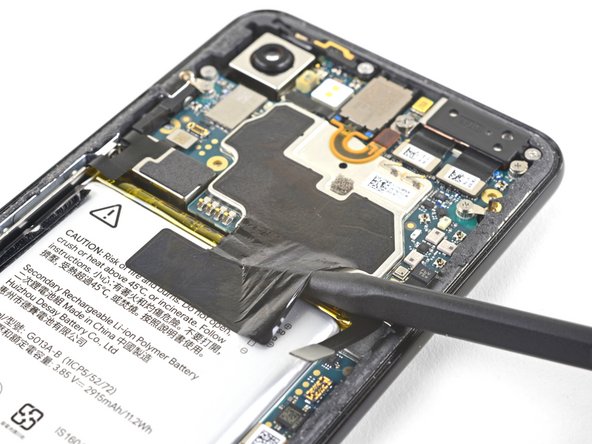
Slide the point of a spudger in the crevice underneath the black tape bridging across the battery and the motherboard.
-
Slide the spudger along the crevice to pry up the tape from the battery side.
-
Carefully peel the tape from the battery and fold it out of the way.
-
-
Bu adım çevrilmemiş. Çevrilmesine yardım edin
-
Use a spudger to pry up and disconnect the following seven press-fit connectors from their motherboard sockets:
-
External buttons connector
-
Top microphone connector
-
Earpiece connector
-
Left squeeze sensor connector
-
Screen connector
-
Right squeeze sensor connector
-
SIM tray connector
-
-
Bu adım çevrilmemiş. Çevrilmesine yardım edin
-
Use the flat of a spudger to carefully pry up and bend the earpiece speaker's flex cable upwards, out of the way of the motherboard.
-
-
Bu adım çevrilmemiş. Çevrilmesine yardım edin
-
Remove the six screws securing the motherboard in place:
-
One 4.2 mm Phillips screw
-
Three 1.9 mm Phillips screws
-
One 4.3 mm Phillips screw
-
One 3.83 mm standoff screw
-
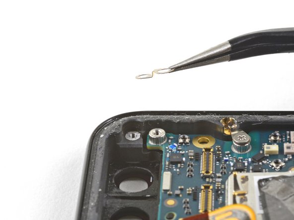
Remove and retain the three small metal grounding clips.
-
-
Bu adım çevrilmemiş. Çevrilmesine yardım edin
-
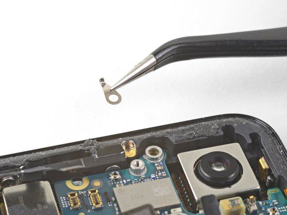
Carefully remove the antenna bracket from the top left edge of the phone.
-
Orient the clips such that the silver side is facing upwards.
-
The teardrop shaped clips should have their points facing towards the phone edge.
-
The double-holed clip dips downwards towards the frame's top-right screw hole.
-
-
Bu adım çevrilmemiş. Çevrilmesine yardım edin
-
Insert the point of a spudger near the top left corner of the motherboard, right below the rear-facing camera.
-
Pry up gently to loosen the motherboard, bending all flex cables away to accommodate for the movement.
-
If the motherboard feels firmly seated, check for any flex cables or screws that may still be connected.
-
-
Bu adım çevrilmemiş. Çevrilmesine yardım edin
-
Insert the spudger underneath the top edge of the motherboard and carefully pry up to loosen the motherboard.
-
-
Bu adım çevrilmemiş. Çevrilmesine yardım edin
-
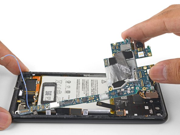
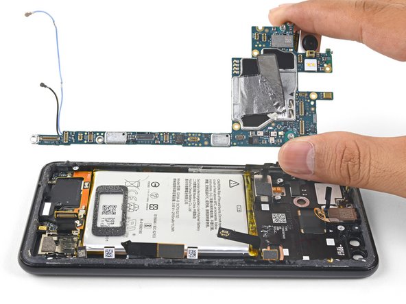
Lift the left edge of the motherboard and carefully swing upwards it towards the right. Carefully push any press connectors snagging the motherboard out of the way.
-
-
Bu adım çevrilmemiş. Çevrilmesine yardım edin
-
Carefully lift the top end of the motherboard away from the frame.
-
Remove the motherboard.
-


İptal et: Bu kılavuzu tamamlamadım.
14 farklı kişi bu kılavuzu tamamladı.


7 Yorum
I followed your instructions to the letter. Got it all put back together, but before affixing the back glass, I powered up the Pixel 3 to make sure all features are working. The touch screen does not work, now, but it did before. Any advice?
Hi Philip,
Does the screen light up? If it doesn’t, I would suggest disconnecting the battery connector and double-checking the display connector to make sure it is properly seated. As I looked into your question, I noticed that the step was missing a disconnection procedure—so thank you! I’ve amended that step.
Hi, I met the same issue as you, the touch didn't work after replacing the mother board. Do you know why? And have you fixed the problem?
Where can I buy the motherboard? Is the 128 GB motherboard different from the 64 GB?