Giriş
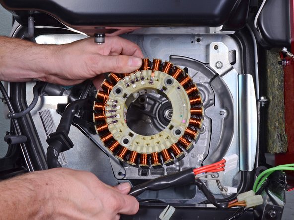
This guide shows how to remove and replace the stator for the Honda EU3000IS1AWK 3000 watt generator.
You will need the following specialty tools in order to complete this guide:
- Flywheel puller kit with metric bolts (in order to remove the rotor)
- Long shaft (at least 5 inches) Phillips #1 screwdriver
Be sure to drain the fuel tank before you begin this guide, and have containers at hand to catch any fuel spillage.
Some images in this guide may show minor discontinuities. They should not affect the overall guide procedure.
Neye ihtiyacın var
-
-
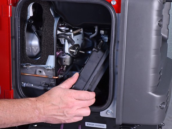
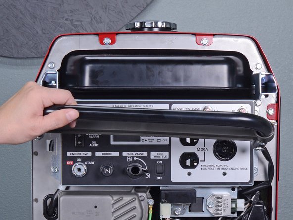
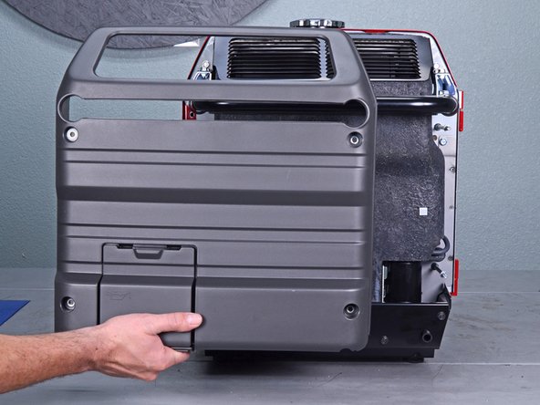
Use a large flathead screwdriver to unlock the maintenance cover.
-
Open the maintenance cover.
-
-
-
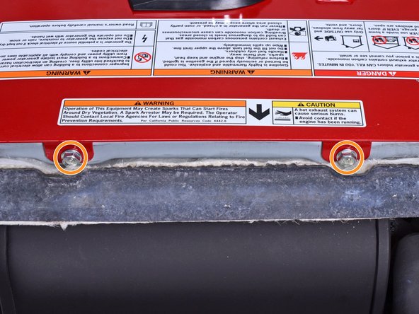
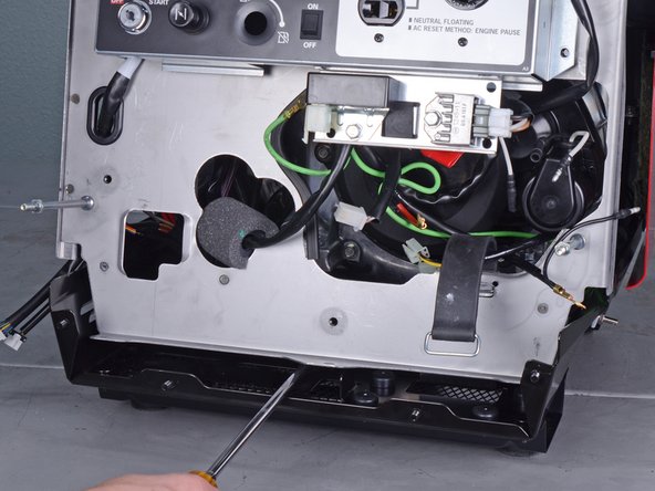
Carefully tilt the generator to its side or back.
-
Use a 10 mm socket to remove the two nuts securing the front bushing mounts to the bottom of the generator.
-
Carefully tilt the generator back to an upright position.
-
-
-
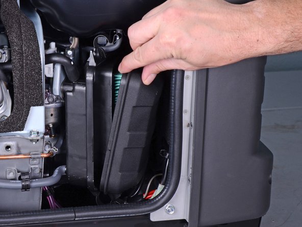
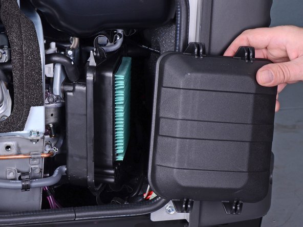
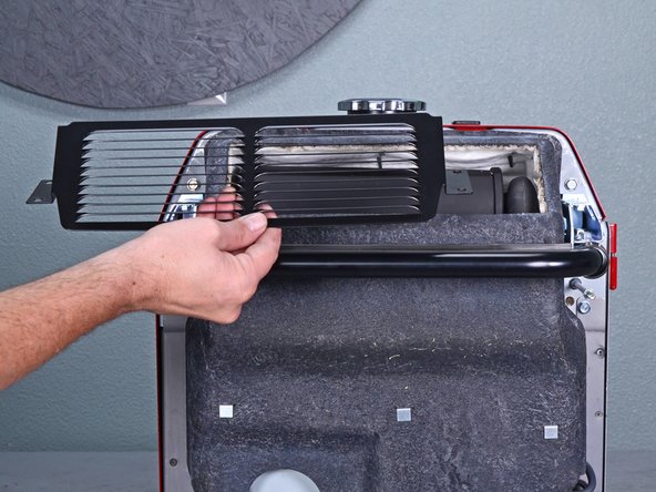
Unlatch the four clips securing the air cleaner cover.
-
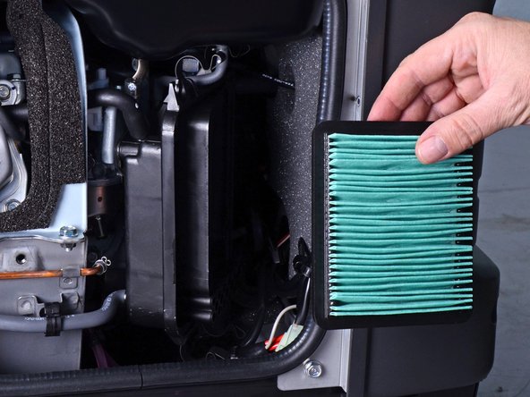
Remove the air cleaner cover.
-
-
-
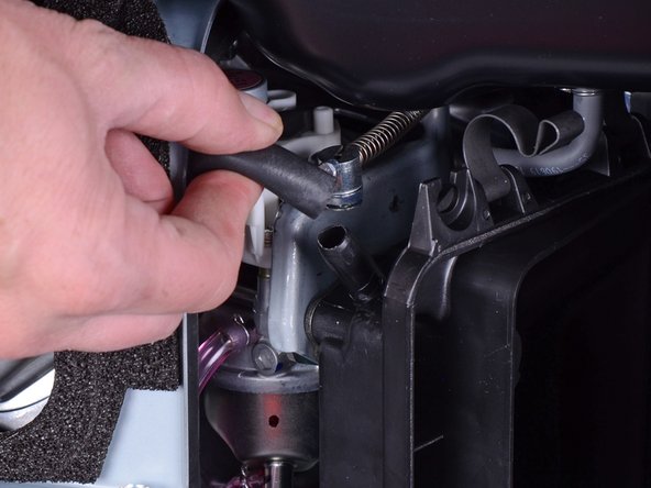
Pull and disconnect the breather tube from the top corner of the air cleaner housing.
-
-
-
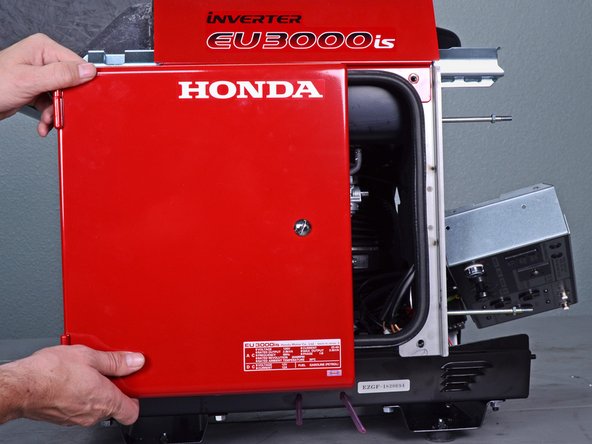
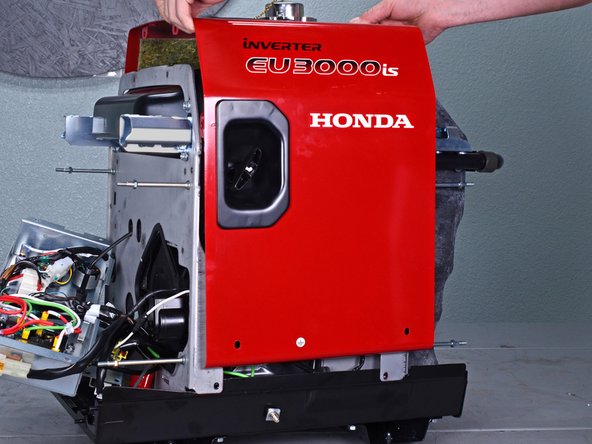
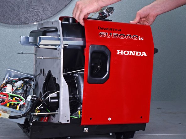
Use a 10 mm socket to remove the four capped nuts securing the front cover.
-
Remove the front cover.
-
-
-
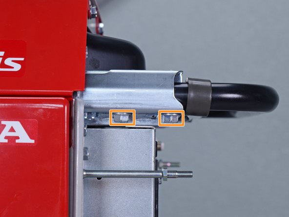
Use a 10 mm socket to remove the four bolts securing the handle to the frame.
-
-
-
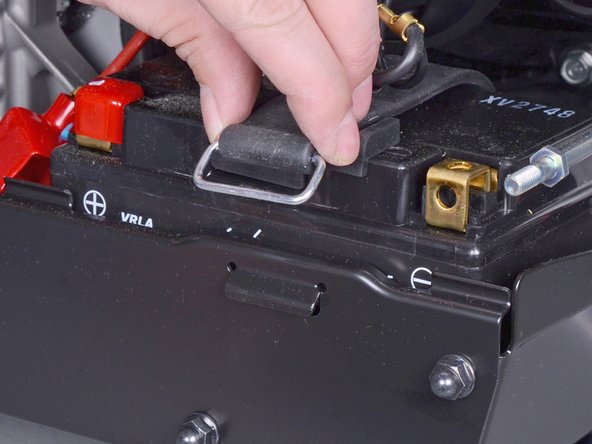
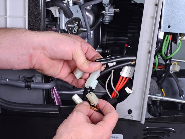
Use an 8 mm socket to disconnect the battery wires from the battery terminals.
-
Disconnect the black negative cable first to prevent the risk of shorting the battery.
-
-
-
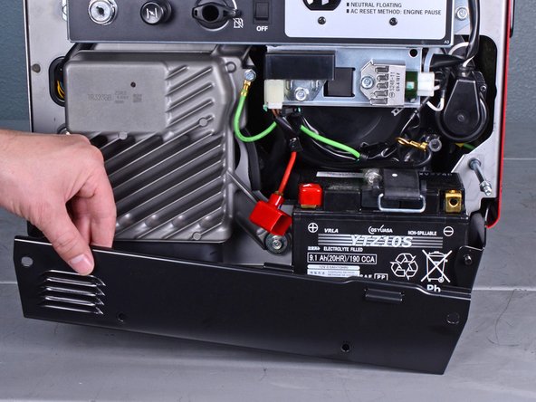
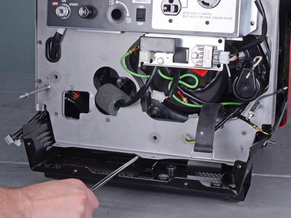
Use a 10 mm socket to remove the four capped nuts securing the lower plate.
-
Remove the lower plate.
-
-
-
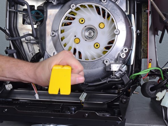
Insert a flathead screwdriver into the top of the brown fuse clip in order to release the fuse holder.
-
Detach the fuse holder from the brown clip.
-
-
-
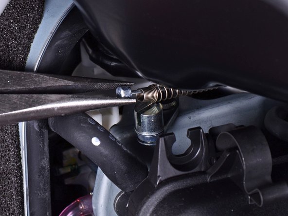
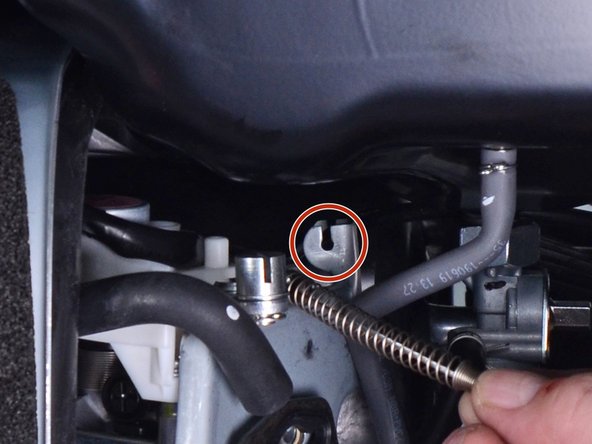
Use pliers to lift and disconnect the choke cable from the choke stay.
-
-
-
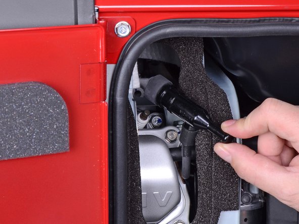
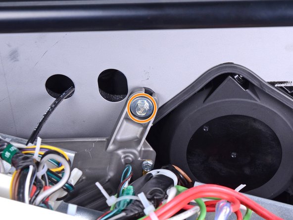
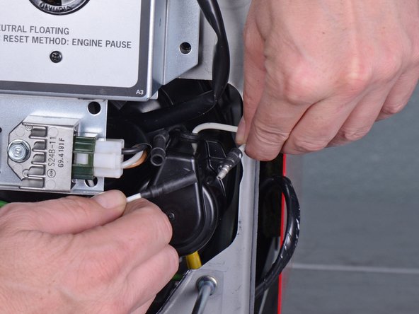
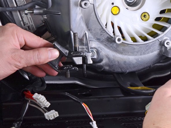
Use a long shaft Phillips screwdriver to remove the deeply recessed screw securing the fuel cutoff switch.
-
-
-
Use a 10 mm socket to remove the four bolts securing the control panel.
-
-
-
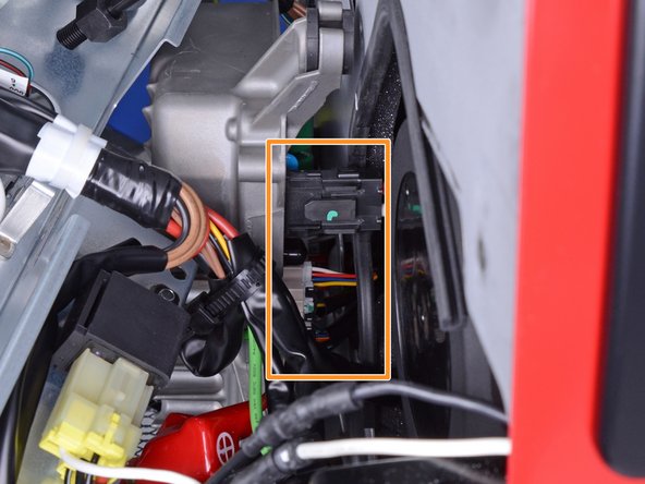
Remove the following bolts securing the inverter:
-
One 8 mm ground bolt
-
Three 10 mm bolts (one behind the control panel)
-
-
-
-
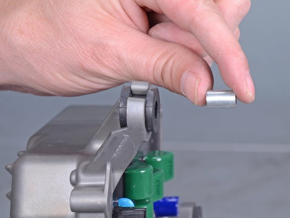
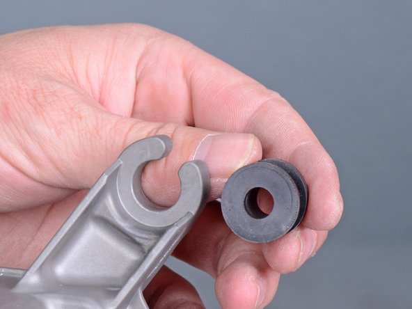
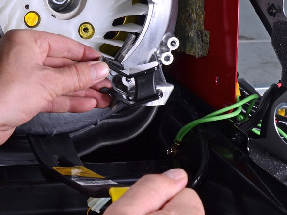
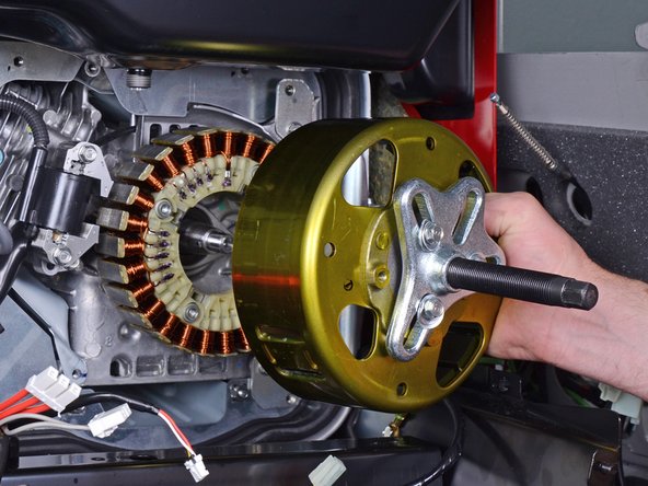
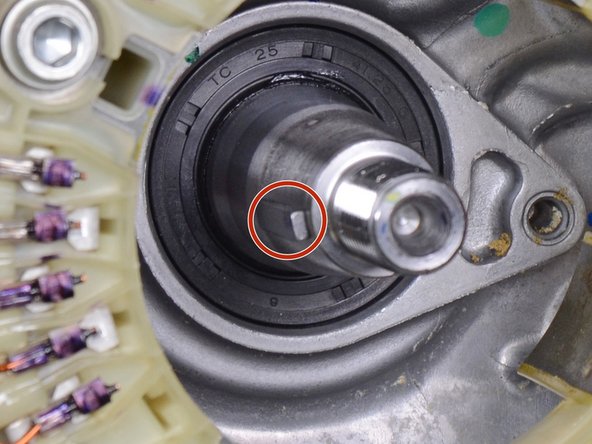
Use a screwdriver to push the metal collar out of the center of the rubber mount.
-
-
-
Use a 10 mm socket to remove the four capped nuts securing the rear cover.
-
Remove the rear cover.
-
-
-
Pull the muffler shroud slightly away from the frame to access the top frame bolts.
-
Use a 10 mm socket to remove the two bolts securing the top edge of the cover.
-
-
-
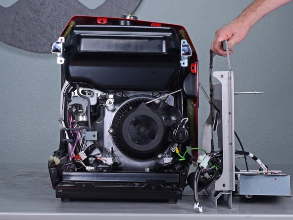
At this point, it may be helpful to temporarily re-attach the control panel back onto the front frame with some 10 mm bolts.
-
-
-
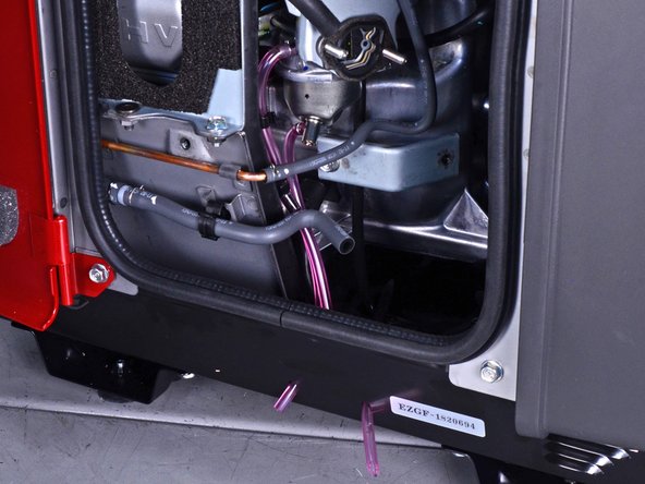
Lift up and release the choke cable's rubber bushing from the choke stay.
-
-
-
Use a 10 mm socket to remove the three frame bolts securing the bottom of the front frame.
-
-
-
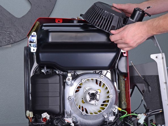
Use a 10 mm socket to remove the three bolts securing the recoil starter.
-
-
-
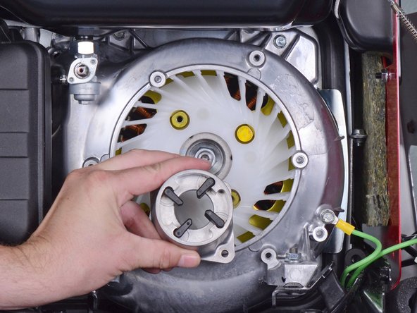
Use a 10 mm socket to remove the two bolts securing the starter pulley.
-
Remove the starter pulley.
-
-
-
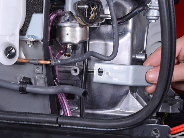
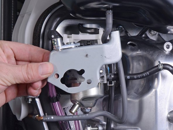
Use a 10 mm socket to remove the bolt securing the air cleaner housing bracket.
-
Remove the air cleaner housing bracket.
-
-
-
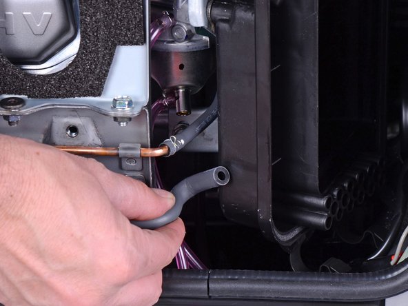
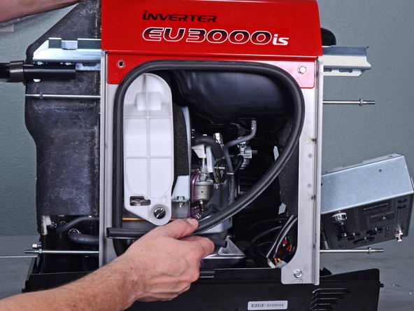
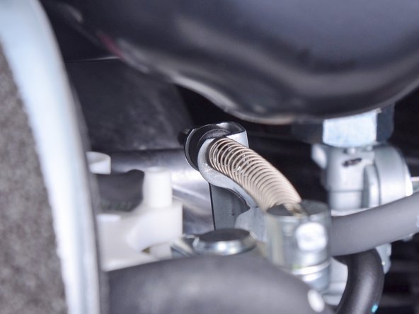
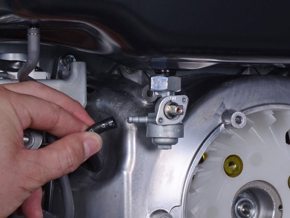
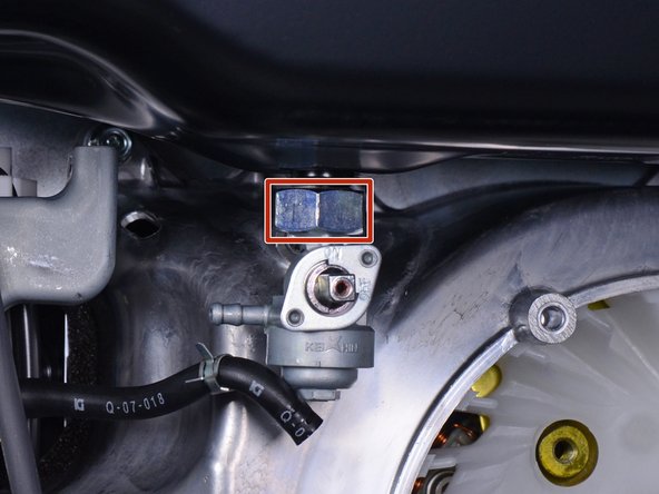
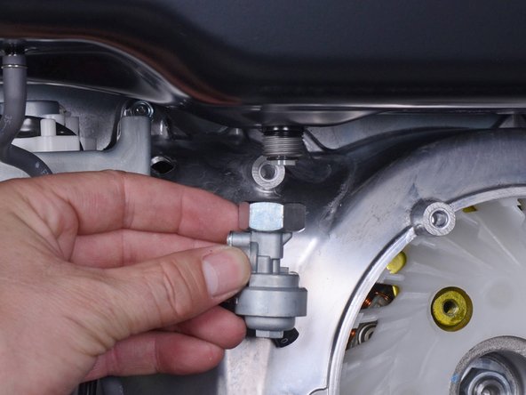
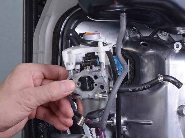
Use pliers to squeeze and loosen the hose clamp securing the carburetor fuel line.
-
Pull and disconnect the carburetor fuel line from the petcock assembly.
-
-
-
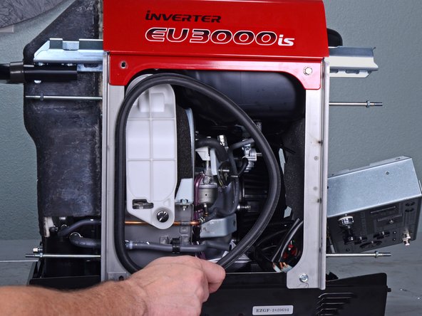
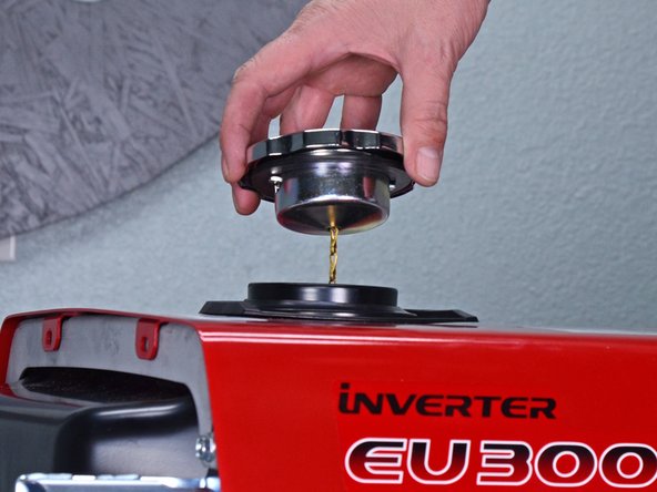
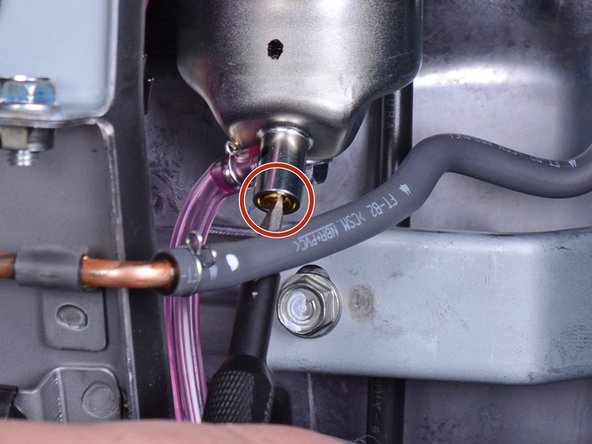
Place a container below the carburetor drain tube to catch the excess fuel.
-
The carburetor drain screw is located at the bottom of the carburetor.
-
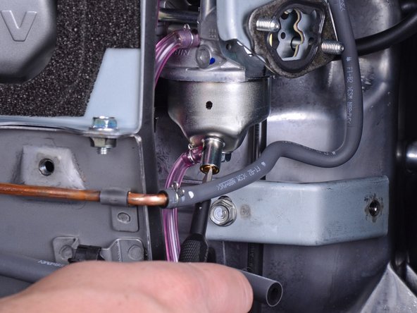
Use a flathead screwdriver to loosen the brass fuel drain screw until fuel begins to drain out of the carburetor.
-
Once you drain the fuel bowl, re-tighten the fuel drain screw.
-
-
-
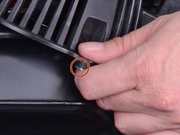
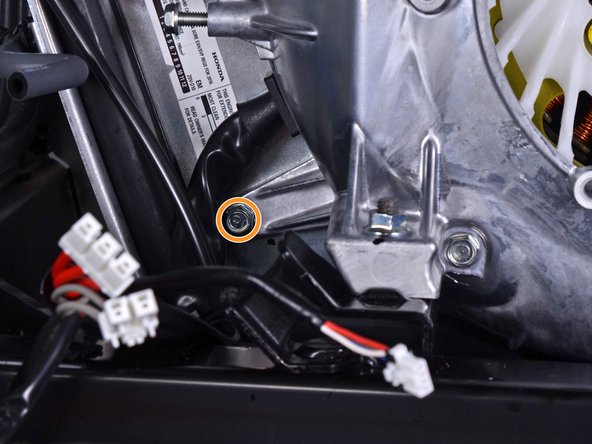
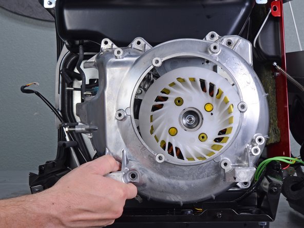
Use a 10 mm socket to remove the seven bolts securing the fan cover:
-
Four bolts on top
-
One recessed bolt in the bottom left corner
-
Two bolts in the bottom right corner
-
-
-
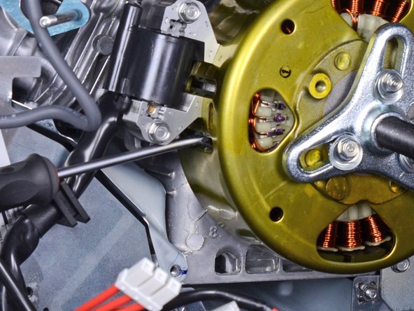
Use a 19 mm socket to remove the nut securing the rotor to the generator shaft.
-
-
-
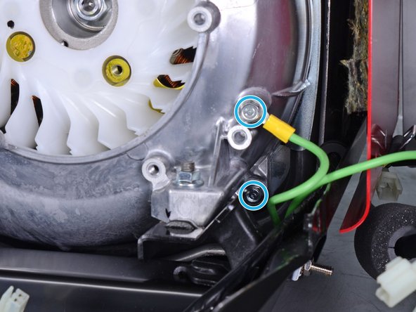
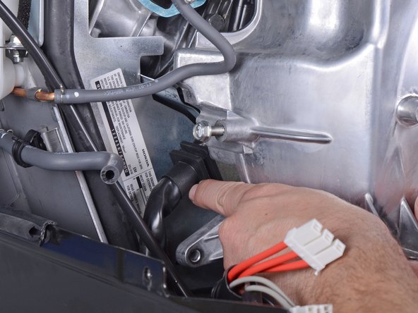
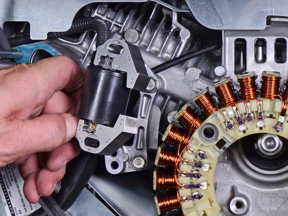
Use a 10 mm socket to remove the two bolts securing the ignition coil.
-
Loosen the ignition coil from the frame.
-
-
-
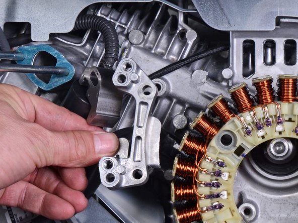
Use a 10 mm socket to remove the two bolts securing the ignition coil bracket.
-
Remove the ignition coil bracket.
-


To reassemble your device, follow these instructions in reverse order.
To reassemble your device, follow these instructions in reverse order.
İptal et: Bu kılavuzu tamamlamadım.
2 farklı kişi bu kılavuzu tamamladı.


3Kılavuz Yorumları
Hy How Are You
I Have Many Time Open EU30is or Eu65is . Thanks For Sharing in Picture Wire Every Steps. I Had Not Agree Your Step, No 76.
Step No.76 (Be careful not to insert the screwdriver too deeply into the slot, or you will damage the stator.)
Not Agree, Please Use Fly Wheel Stoper Holder. or Special Tool, Thank You.
Allah Blessings You.
I too think step 76 is a recipe for destroying the flywheel. The shock and distortion of using a flywheel puller in this manner will cause the magnets to break away from the flywheel. Instead undo the flywheel bolt a few turns and use a thick bar of metal with 7mm holes to coincide with the recoil cup holes in the flywheel. Use bolts through the bar into the threaded m6 recoil cup holes in the flywheel to put a bit of pressure on the flywheel nut with the bar. Then tap the bar sharply with a hammer above the flywheel nut. The flywheel will disengage easily. While doing this be careful that the bolts do not go far enough into the flywheel to damage the windings. You should be able to align the threaded holes with the heads of the bolts holding the stator to protect against this possibility.
Says nothing about measuring the stator before conclude a defect stator before dissemble it, how many OHM should it be measured at the 3 phase connector ?