Giriş
A guide on how to replace the top PCB assembly on a Logitech G700s mouse.
Neye ihtiyacın var
-
-
Remove the batteries from the mouse.
-
Use a plastic opening tool to peel up the four mouse feet.
-
-
-
Pull the top of the mouse off of the bottom half.
-
Unplug the programmable buttons from the motherboard.
-
-
-
-
Remove the black pin that holds the scroll wheel to the motherboard.
-
The protrusion on the bottom side of the pin clicks into the dimple on the base.
-
I find the easiest way to remove the pin is to use the pointy end of the spudger to push on this end of the pin.
-
-
-
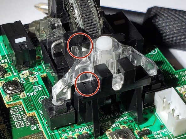
First, lift the assembly from the back (green arrow), while keeping the front clear plastic part resting on the springs (red circle).
-
Then, while pulling it toward the back very slightly, carefully lift the front part off the springs.
-
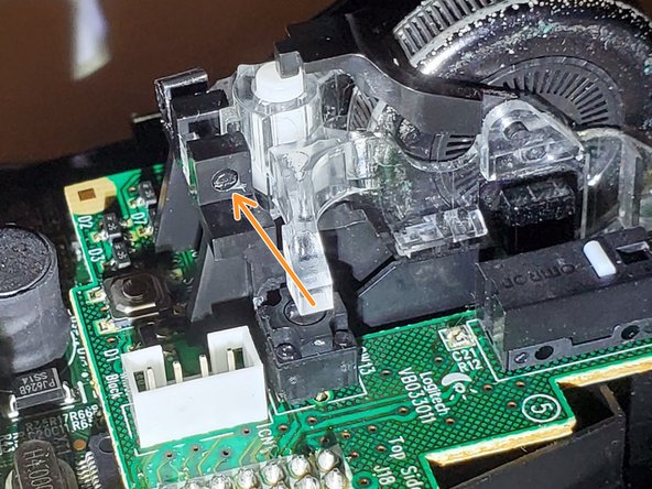
The clear front part has a hole that attaches onto a clear nibble just below the bracket (blue arrow in second picture) for the scrollwheel to pivot left and right for the left and right scroll function.
-
Though the pivot point isn't attached too deeply. When reassembling, align the circular marks in the front to the springs, then press the back side down into the holder and it will self align.
-
Remove the springs and keep them safe.
My problem was dirt accumulated in the clear plastic case of the wheel, making wheel hard to spin. I was able to disassemble and reassemble OK, but the difficulty was “hard”, and it took 20-30 minutes.
Didn’t thought about taking photos and I’m not going to disassemble this again, maybe after another 2.5 years of use. Still, here’s couple of tips.
Two tiny springs in the wheel assembly are tricky to assemble back correctly. Pay attention where each end of the spring is. You’ll need to pre-load them the same way or you gonna break the “clicky versus smooth wheel” mechanical button.
The wheel axle is non removable. To detach the wheel, you need to apply outwards forces on the two clear plastic things holding ends of the axle. I used 2 flat screwdrivers, inserting them along the sides of the wheel. It’s easy to break plastic part by applying too much force, but I was lucky.
I had this same issue, but what I did is take a piece of paper towel and used tweezers to force it between the mouse and the clear plastic casing. Then by forcefully scrolling, it pushed both the paper towel, and the dirt, out of the scroll wheel mechanism.
-
-
-
Desolder the header pins. Desolder while the screws and mounting hardware in the next two steps are still attached, so the board is more stable.
-
Look straight down and check that there most of the solder between the pin and the sidewall is removed. Push each pin sideways to make sure it is detached.
-
If it looks mostly clear but the pin is still attached, try pushing the pin to the opposite wall (where it is clearly detached) with a moderate amount of force. (Do not force it too much though or you risk damaging the through hole plating)
-
If it doesn't budge with a moderate amount of force, try using the iron to push on the pin the same way. If it attaches to another part, then the solder isn't sucked up enough.
-
Optionally, you may want to mod the PCB to use a socket to connect between the top and bottom, so it will be easier to access in the future. You will need to replace or cut short the header pins. It uses 2.0mm pitch 2x7 headers. There is approximately 7.2mm between the boards. I used Molex 87758-1450 pins and Amphenol 63453-114LF socket.
Is there a guide somewhere on how to do the socket mod for the connection between the top and bottom PCBs?
Follow the bottom PCB assembly replacement guide then desolder the header completely, and install the parts mentioned in this step.
Though desoldering the header on the bottom board can be much more difficult due to the holes being plated through holes, so it's much more difficult to get the solder out. I used a piece of desoldering braid loaded with solder and a blade soldering tip to heat all joints and remove the header. Very fiddly process.
If you want to experiment you can try snipping the headers short (without disassembling the bottom board) by maybe 2~3mm, and filing the sharp edges down a bit. Though beware of metal dust/clippings that might short out components.
-
-
-
Remove the two Phillips #00 screws from the motherboard.
-
Remove the metal bracket
you need to go over the connection between the boards poor shwing to just break the board
-
-
-
Remove the two Phillips #00 screws.
-
Next, remove the plastic mount for scroll wheel.
-
The top button board can now be removed.
-
If you have modded your mouse to use socket instead of soldered connections, lift the board up from the locations indicated by the yellow circles to avoid breaking the PCB. When reassembling, first align the two center posts that the scroll wheel mount attaches to the holes, then press down on the header area.
-


To reassemble your device, follow these instructions in reverse order.
To reassemble your device, follow these instructions in reverse order.
İptal et: Bu kılavuzu tamamlamadım.
6 farklı kişi bu kılavuzu tamamladı.
Ekip

USF Tampa, Team S2-G3, Nance Spring 2018 USF Tampa, Team S2-G3, Nance Spring 2018 üyesi
USFT-NANCE-S18S2G3
4 Üyeler
15 adet Kılavuz yazıldı
9 Yorum
lol, you broke the PCB and kept it covered with your thumb all the time as if you don’t need to desolder 14 pins before step 6…
Yes. I wonder why they excluded that part ^^,
What Youri said. Plus be warned de-soldering the pins is extremely difficult to do without the proper tools, or you risk ripping the copper solder pads of the upper board when doing so (sadly that happened to me). I’d suggest trying solder wick rather than a solder sucker as its a fiddly job.
You are also going to need some fine soldering skills when replacing the board.
Wonderful. Just skip the hardest part. Desodering the two PCBs by breaking them apart.
The harder step is to unsolder the 14pins, add over tins on the weldering and use unsolder copper string to quit it properly. Thanks to the Chase tisinger for the article.
Hello
does anyone know the reference # of the scroll sideways switches of this mouse ?
Thank you
Solder Wick is your friend. If you can’t afford a professional solder sucker do your self a favor and use a high wattage small pointed tip with solder wick. This from someone that started out repairing the Summit calculator working thru collage. I still have the Weller soldering station I used, 47 years ago.