Bu sürüm, hatalı düzenlemeler içerebilir. En son doğrulanmış bellek kopyası dönün.
Neye ihtiyacın var
-
Bu adım çevrilmemiş. Çevrilmesine yardım edin
-
Insert a SIM card eject tool, bit, or a straightened paperclip into the small hole below the SIM card tray, located near the rear cameras on the edge of the phone.
-
Press firmly to eject the tray.
-
-
Bu adım çevrilmemiş. Çevrilmesine yardım edin
-
Remove the two 2.6 mm T2 screws straddling the USB-C port on the bottom edge of the phone.
-
-
Bu adım çevrilmemiş. Çevrilmesine yardım edin
-
Display panel seam: This seam is part of the display assembly. Do not pry at this seam, or you will separate and damage the display panel.
-
Frame seam: This is where the plastic frame meets the back cover. Only pry at this seam.
-
There are twelve clips that hold the frame against the rear case. Be aware of their location as you pry the back cover off in the following steps.
-
-
Bu adım çevrilmemiş. Çevrilmesine yardım edin
-
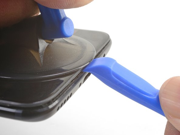
Place a suction cup near the bottom edge of the display.
-
Pull on the suction cup with strong steady force.
-
Press the edge of an opening tool straight into the frame seam near the suction cup until the edge wedges between the plastic frame and the back cover's lip.
-
-
Bu adım çevrilmemiş. Çevrilmesine yardım edin
-
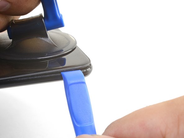
Once the opening tool's edge is wedged in position, carefully slide the tool along the bottom edge of the phone.
-
Carefully guide the opening tool around the left corner of the phone while keeping the tool's edge within the seam.
-
-
Bu adım çevrilmemiş. Çevrilmesine yardım edin
-
Lever the opening tool to release the first clip from the frame.
-
-
Bu adım çevrilmemiş. Çevrilmesine yardım edin
-
Continue sliding the opening tool along the long edge, releasing the clips along the way.
-
-
Bu adım çevrilmemiş. Çevrilmesine yardım edin
-
With the bottom and left edge of the phone freed, gently wiggle the frame to release the top and right edge clips.
-
Align the top edge of the frame to the back cover and ensure that the top clips slip into place.
-
Squeeze along the long edges of the phone to snap the remaining clips into place.
-
-
Bu adım çevrilmemiş. Çevrilmesine yardım edin
-
With all the clips released, flip the phone over so that the display is face-down.
-
Swing the back cover around and rest it on top of the exposed frame.
-
-
Bu adım çevrilmemiş. Çevrilmesine yardım edin
-
Remove the 2.6 mm Phillips screw holding the cable bracket above the battery in place.
-
Lift up and remove the cable bracket.
-
-
Bu adım çevrilmemiş. Çevrilmesine yardım edin
-
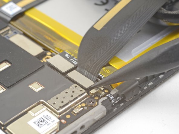
Use the point of a spudger to pry up and disconnect the back cover flex cable from its socket.
-
-
Bu adım çevrilmemiş. Çevrilmesine yardım edin
-
Use the point of a spudger to pry up and disconnect the battery connector from its socket.
-
-
Bu adım çevrilmemiş. Çevrilmesine yardım edin
-
Remove the six 2.6 mm Phillips screws securing the loudspeaker to the frame.
-
-
Bu adım çevrilmemiş. Çevrilmesine yardım edin
-
Insert the flat end of a spudger into the corner of the loudspeaker assembly and pry slightly, loosening the loudspeaker from its recess.
-
-
Bu adım çevrilmemiş. Çevrilmesine yardım edin
-
Use the point of a spudger to pry up and disconnect the interconnect flex cable from the socket.
-
-
-
Bu adım çevrilmemiş. Çevrilmesine yardım edin
-
Brace the phone frame against the table.
-
Using a strong, steady force, pull the green pull tab upwards until the battery loosens from its recess.
-
Swing the battery completely out of its recess and pull it off of the plastic liner.
-
-
Bu adım çevrilmemiş. Çevrilmesine yardım edin
-
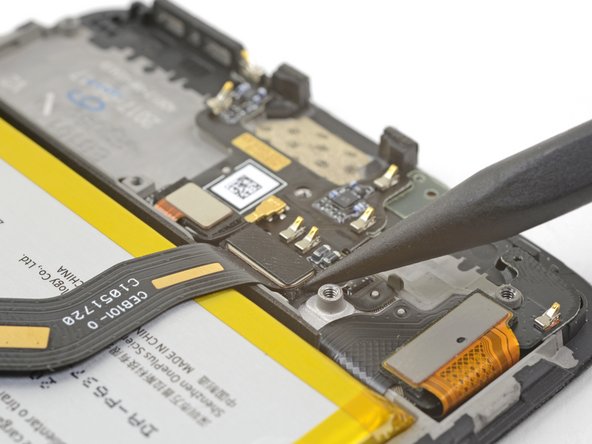
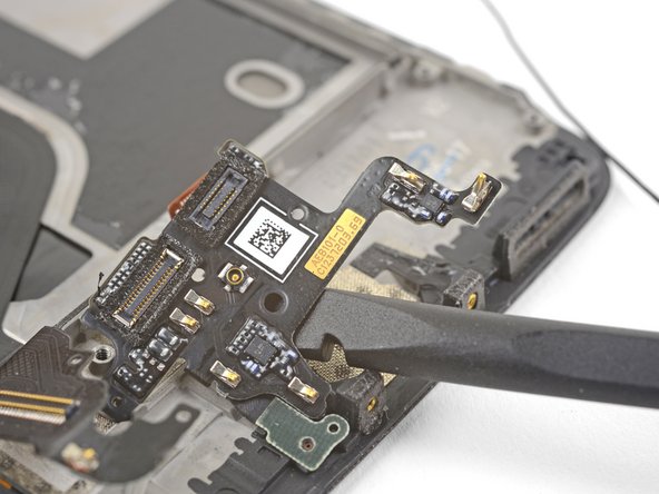
Use the point of a spudger the pry up and disconnect the fingerprint scanner connector from its socket on the daughterboard.
-
-
Bu adım çevrilmemiş. Çevrilmesine yardım edin
-
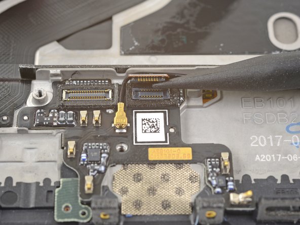
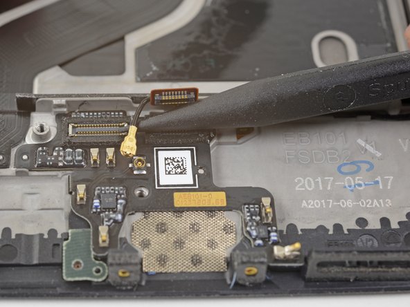
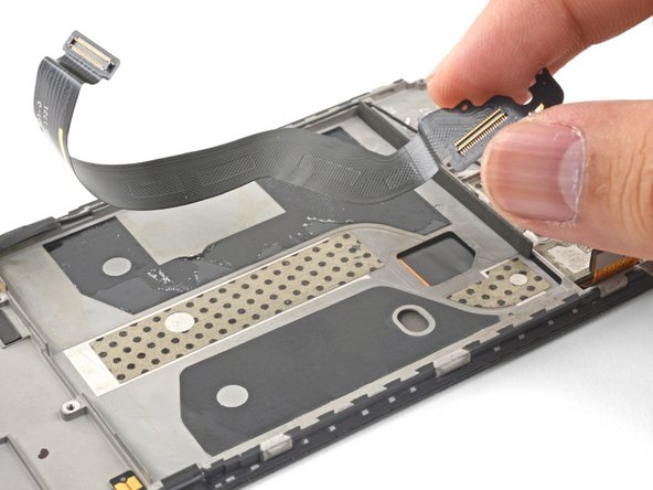
Slip the point of a spudger underneath the antenna interconnect cable and pry up to disconnect it from its socket on the daughterboard.
-
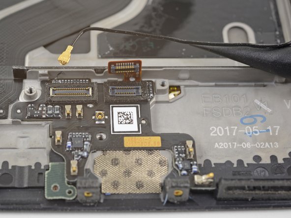
De-route the antenna interconnect cable out of the way of the daughterboard.
-
-
Bu adım çevrilmemiş. Çevrilmesine yardım edin
-
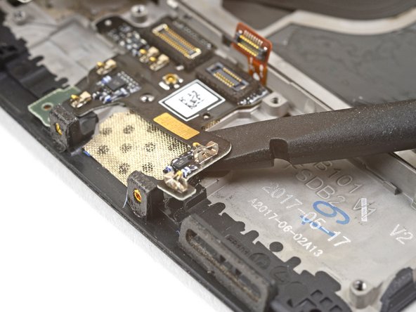
Insert the edge of a flat end of the spudger underneath the microphone board and twist slightly to release the board's adhesive.
-
-
Bu adım çevrilmemiş. Çevrilmesine yardım edin
-
Slide the flat end of a spudger or the point of an opening pick underneath the daughterboard near its right edge.
-
Gently pry to loosen the daughterboard from its recess.
-
-
Bu adım çevrilmemiş. Çevrilmesine yardım edin
-
Insert the flat end of a spudger underneath the daughterboard, this time approaching it from the bottom.
-
Twist and slide the spudger slightly to release the daughterboard from its recess.
-
-
Bu adım çevrilmemiş. Çevrilmesine yardım edin
-
Slide the flat end of a spudger underneath the tape covering the fingerprint scanner.
-
Lift up to pry and remove the tape.
-
-
Bu adım çevrilmemiş. Çevrilmesine yardım edin
-
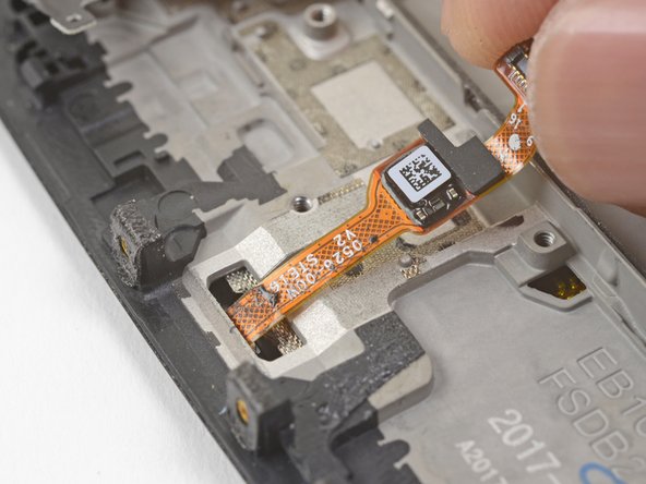
Use your finger to gently lift up the connector end of the fingerprint scanner. Pull upwards slowly. Do not pull directly away from the fingerprint scanner.
-
Keep pulling upwards until the fingerprint scanner cable is freed from its recess.
-
-
Bu adım çevrilmemiş. Çevrilmesine yardım edin
-
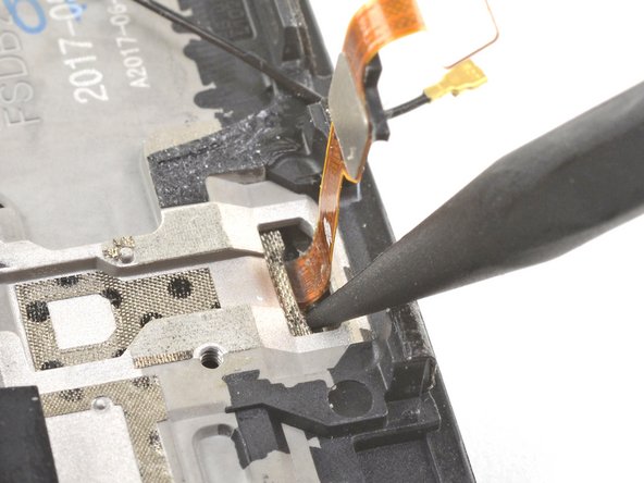
Insert the point of a spudger into the marked areas on either side of the flex cable, and push until the fingerprint scanner is loosened from its recess.
-
-
Bu adım çevrilmemiş. Çevrilmesine yardım edin
-
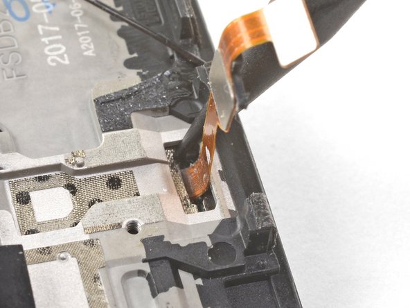
Once the fingerprint scanner is loosened from its recess, carefully thread its flex cable through the cutout, out of the front of the display.
-
Remove the fingerprint scanner.
-
-
Bu adım çevrilmemiş. Çevrilmesine yardım edin
-
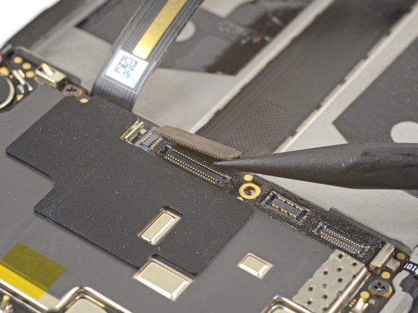
Use the point of a spudger to pry up and disconnect the display interconnect cable from its socket near the bottom edge of the motherboard.
-
-
Bu adım çevrilmemiş. Çevrilmesine yardım edin
-
Slide the point of a spudger underneath the antenna interconnect cable that is connected to the motherboard above the vibration motor.
-
Pry up to disconnect the cable from its socket.
-
De-route the cable out of its motherboard grounding clip and move it out of the way.
-
-
Bu adım çevrilmemiş. Çevrilmesine yardım edin
-
Slide the point of a spudger under the small square antenna connector connected to the motherboard near the top edge.
-
Pry up to disconnect the antenna connector from its socket.
-
-
Bu adım çevrilmemiş. Çevrilmesine yardım edin
-
Remove the following seven 2.6 mm Phillips screws securing the motherboard:
-
-
Bu adım çevrilmemiş. Çevrilmesine yardım edin
-
Use your fingers to lift up the top edge of the motherboard.
-
Lift the motherboard out of its recess and remove it.
-
-
Bu adım çevrilmemiş. Çevrilmesine yardım edin
-
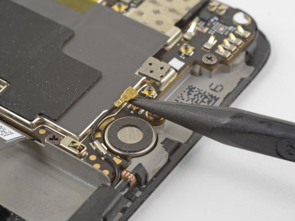
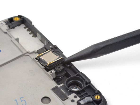
Insert the point of a spudger under the top right corner of the earpiece module and pry up, loosening the module from its recess.
-
-
Bu adım çevrilmemiş. Çevrilmesine yardım edin
-
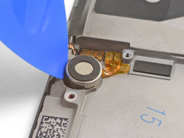
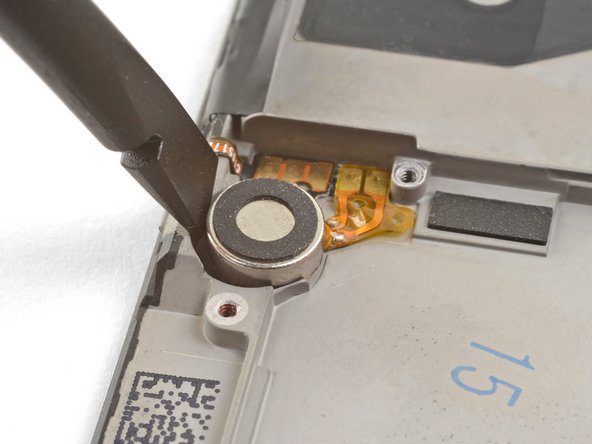
Wedge the point of an opening pick between the vibration motor and the frame and push downward to loosen the vibration motor from its recess.
-
Once the vibration motor is slightly loosened, you can wedge the flat end of a spudger between the motor and the frame to help free it from its recess.
-
-
Bu adım çevrilmemiş. Çevrilmesine yardım edin
-
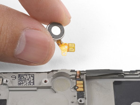
Slide the point of an opening pick underneath the vibration motor's flex pad and gently pry it off of the frame.
-
Remove the vibration motor.
-
-
Bu adım çevrilmemiş. Çevrilmesine yardım edin
-
Use tweezers or the point of a spudger to pry up and remove the black tape covering the volume buttons on the right edge of the phone.
-
Repeat the process with the black tape covering the power button on the left edge of the phone.
-
-
Bu adım çevrilmemiş. Çevrilmesine yardım edin
-
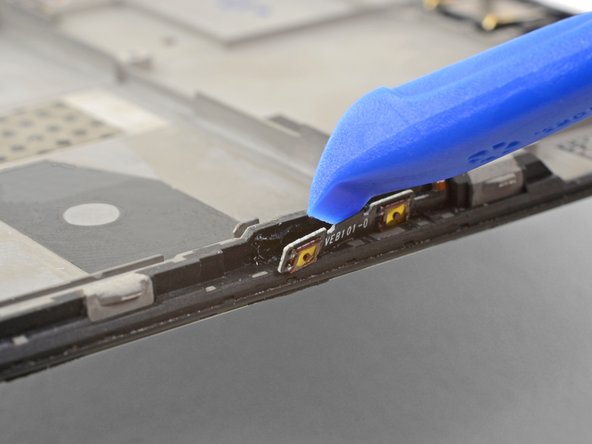
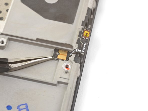
Use the edge of an opening tool to gently pry the volume button board away from the frame.
-
Continue prying until you loosen the volume button board from the frame.
-
-
Bu adım çevrilmemiş. Çevrilmesine yardım edin
-
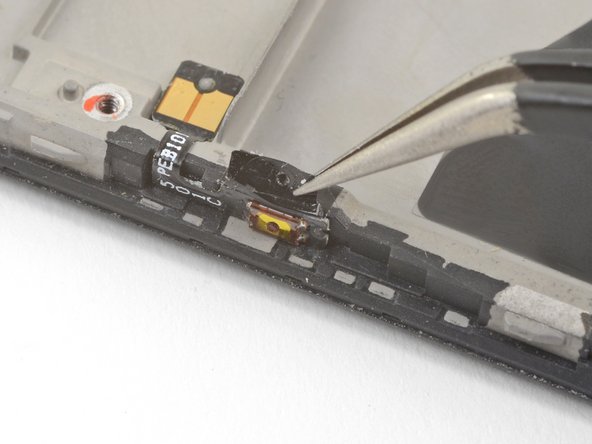
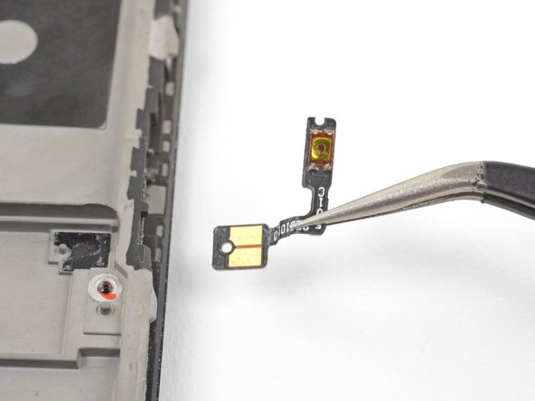
Squeeze the tweezer tips together and insert the point underneath the volume button board's contact pad near the top right edge of the frame.
-
Pry upwards to loosen the contact pad from the frame.
-
Remove the volume buttons.
-
-
Bu adım çevrilmemiş. Çevrilmesine yardım edin
-
Repeat the previous two steps to remove the power button from the left edge of the frame.
-
-
Bu adım çevrilmemiş. Çevrilmesine yardım edin
-
Peel and remove the plastic battery liner from the frame.
-
-
Bu adım çevrilmemiş. Çevrilmesine yardım edin
-
Use the point of a spudger to pry up the display connector from its socket near the bottom left corner of the frame.
-
-
Bu adım çevrilmemiş. Çevrilmesine yardım edin
-
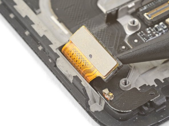
Insert the flat end of a spudger underneath the display interconnect cable socket, near where it connected with the display connector in the bottom left corner of the frame.
-
Pry upwards and slide the spudger underneath the cable to loosen the cable from the frame.
-
-
Bu adım çevrilmemiş. Çevrilmesine yardım edin
-
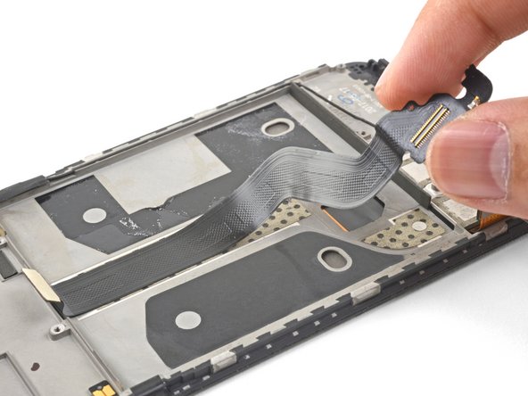
Grasp the loosened end of the display interconnect cable with your fingers and pull upwards, releasing the cable from the frame.
-
Remove the display interconnect cable.
-
-
Bu adım çevrilmemiş. Çevrilmesine yardım edin
-
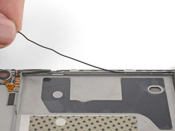
Use your fingers to lift and de-route the antenna interconnect cable from its groove on the right edge of the frame.
-
Transfer the antenna interconnect cable to the new frame.
-
-
Bu adım çevrilmemiş. Çevrilmesine yardım edin
-
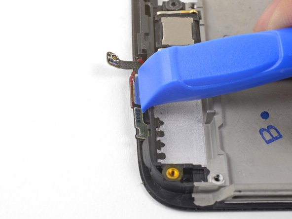
Use the edge of an opening tool to push the back cover antenna connector away from the frame. It is located on the top edge of the frame.
-
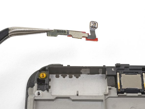
Remove the back cover antenna connector.
-
If you are transferring the connector onto a replacement frame, peel the blue liner on the top edge of the replacement frame before sticking the connector onto the edge.
-
-
Bu adım çevrilmemiş. Çevrilmesine yardım edin
-
The bare screen and digitizer assembly remains.
-
Transfer all of the parts you removed in the previous steps from the old assembly to the new one.
-


İptal et: Bu kılavuzu tamamlamadım.
32 farklı kişi bu kılavuzu tamamladı.


17 Yorum
Nice. But where do you get the replacement part from?
Dear Christos, hope it is not too late, you can check Oneplus 5 screen replacement from Witrigs
HI . Do I need to buy an original screen and digitizer for my oneplus 5?
I'm from Argentina and on EBAY I do not see ORIGINAL parts
Can someone help me?
Hi Joselo,
You do not need an original, but that is probably the best quality. The original screen is AMOLED. There are also OLED and LCD replacement screens. These will not be as bright as the original AMOLED panel.
Hi, I need to know if this screen is like the original (Amoled) or not, and approximately how long it takes to send by mail to Miami Florida. Thank you OnePlus 5 Screen