Bu sürüm, hatalı düzenlemeler içerebilir. En son doğrulanmış bellek kopyası dönün.
Neye ihtiyacın var
-
Bu adım çevrilmemiş. Çevrilmesine yardım edin
-
Remove both of the 3 mm screws on the bottom of the camera connected to the side panel.
-
-
Bu adım çevrilmemiş. Çevrilmesine yardım edin
-
Remove the remaining 3 mm screw holding on the side panel and remove the panel entirely.
-
-
Bu adım çevrilmemiş. Çevrilmesine yardım edin
-
On the opposite side of the camera, remove the two 3 mm screws.
-
Remove the bottom side panel and place it with its respective 3 mm screw.
-
-
-
Bu adım çevrilmemiş. Çevrilmesine yardım edin
-
Remove the front panel (the panel around the lens casing) from the camera.
-
Remove the two ribbon cables connected to the back panel (the panel this the LCD screen) by lifting up on their respective tabs and gently pulling out the cord.
-
Remove the back panel from the camera.
-
-
Bu adım çevrilmemiş. Çevrilmesine yardım edin
-
Remove the top control panel (connected to the flash battery) from the camera.
-
-
Bu adım çevrilmemiş. Çevrilmesine yardım edin
-
Locate and remove the silver 2mm screw on the protection panel.
-
Remove the three black 8mm screws that remain.
-
Proceed to remove the protection panel entirely.
-
-
Bu adım çevrilmemiş. Çevrilmesine yardım edin
-
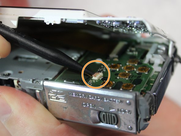
Insert the flat end of a plastic spudger underneath the motherboard and twist. This will disconnect the board from the device and allow it to be removed.
-
-
Bu adım çevrilmemiş. Çevrilmesine yardım edin
-
Use the pointed end of the spudger to lift the black tabs holding the ribbon cable connected to the photoreceptor in place.
-
-
Bu adım çevrilmemiş. Çevrilmesine yardım edin
-
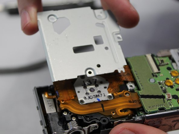
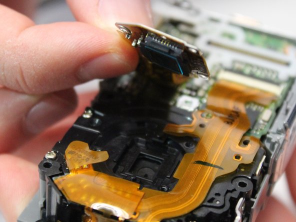
Remove the three 3mm screws holding the photoreceptor in place.
-
Carefully lift the photoreceptor, disconnecting the ribbon cable and remove the photoreceptor from the device.
-


İptal et: Bu kılavuzu tamamlamadım.
Bir başkası bu kılavuzu tamamladı.
Ekip

Baylor, Team S2-G3, Johnson Spring 2018 Baylor, Team S2-G3, Johnson Spring 2018 üyesi
BU-JOHNSON-S18S2G3
3 Üyeler
6 adet Kılavuz yazıldı