Bu sürüm, hatalı düzenlemeler içerebilir. En son doğrulanmış bellek kopyası dönün.
Neye ihtiyacın var
-
Bu adım çevrilmemiş. Çevrilmesine yardım edin
-
Remove 4 screws from the right side of the camera.
-
There are two 3.4mm screws at the top.
-
There are two 2.2mm screws at the bottom.
-
-
Bu adım çevrilmemiş. Çevrilmesine yardım edin
-
Remove the single 3.4mm screw on the left side of the camera.
-
-
Bu adım çevrilmemiş. Çevrilmesine yardım edin
-
Remove 5 screws from the base of the camera.
-
There are two 2.2mm screws next to the battery compartment.
-
There are three 4mm screws around the tripod mount.
-
-
-
Bu adım çevrilmemiş. Çevrilmesine yardım edin
-
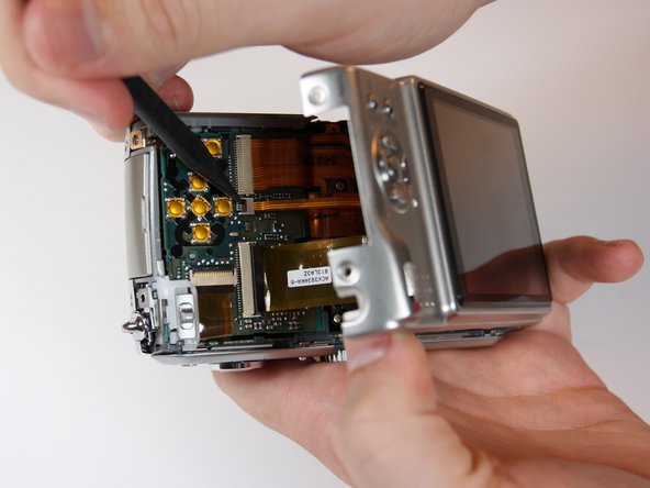
Detach both ribbon cables using a spudger.
-
Use the tip of the spudger to lift the black clip upward, unlocking the ribbon cable.
-
-
Bu adım çevrilmemiş. Çevrilmesine yardım edin
-
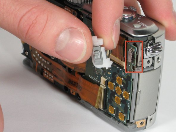
Use the spudger to remove the ribbon cable connecting the lens casing to the circuit board by lifting up the black clip.
-
Carefully remove the function switch cover. This unit snaps on and off.
-
-
Bu adım çevrilmemiş. Çevrilmesine yardım edin
-
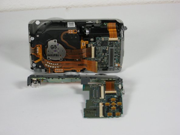
Carefully unsnap the front logic board from the rear logic board using a spudger.
-
-
Bu adım çevrilmemiş. Çevrilmesine yardım edin
-
Slide the entire top part of the camera that is attached to the logic board, horizontally away from the camera.
-
-
Bu adım çevrilmemiş. Çevrilmesine yardım edin
-
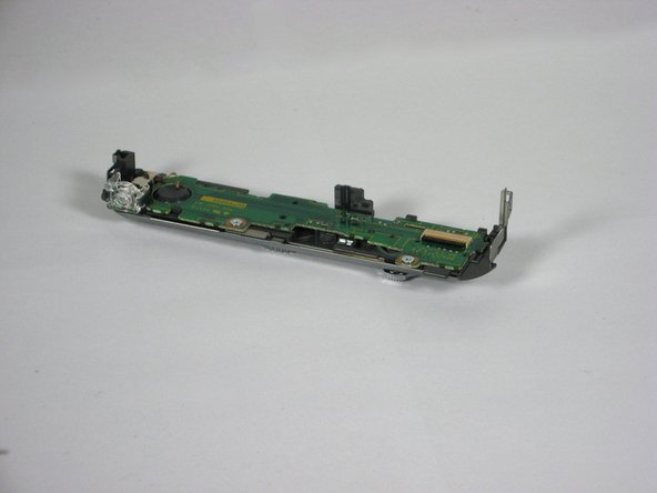
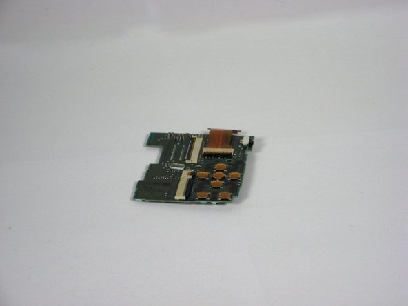
Remove the ribbon cable from the top connection panel by unlocking the black clip with a spudger.
-
This leaves you with the logic board and the top connection panel separate and free from the camera
-


Ekip

Cal Poly, Team 9-21, Regan Fall 2010 Cal Poly, Team 9-21, Regan Fall 2010 üyesi
CPSU-REGAN-F10S9G21
4 Üyeler
14 adet Kılavuz yazıldı