Giriş
Changing the USB port for this model is tricky.
One option would be to replace the connector only, but a resin glue makes it difficult to unsolder the USB connector.
I therefore decided to replace the entire PCB.
However, but this proved to be also really tricky because the PCB is a rigid-flex board with a lot of very tiny flex parts, and I ended up braking the flex part around the jack connector while attempting to remove the PCB. I also damaged the screen while attempting to lift the glass.
So carry out this procedure with great caution!
Neye ihtiyacın var
-
-
Insert a SIM card eject tool, a SIM eject bit or a straightened paper clip into the hole on the SIM tray located at the left side of the phone.
-
Press firmly to eject the tray.
-
Remove the SIM card tray.
-
-
-
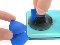
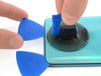
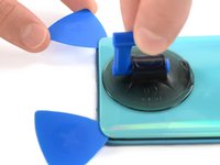
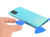
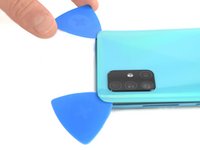
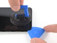
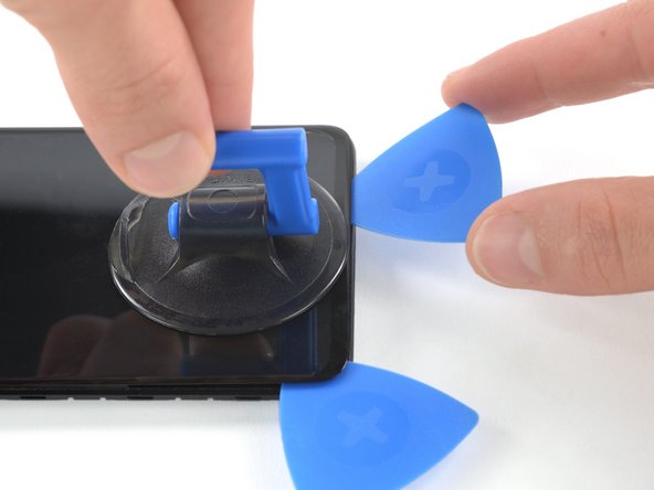
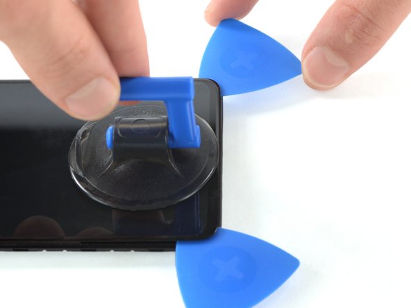
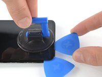
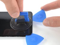
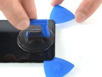
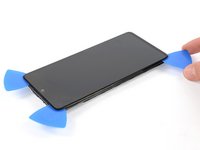
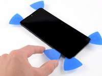
Insert the tip of an opening pick between the frame and the back cover at the bottom of the phone near the USB-C port.
-
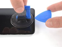
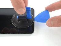
If you can't get between the back cover and midframe with your opening pick, you can use a suction handle or strong tape to pull up the back cover to create a gap.
-
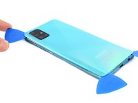
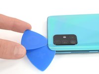
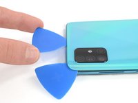
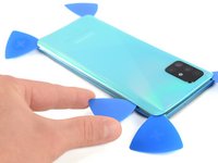
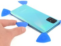
Slide the opening pick to the bottom right corner and leave it there.
-
-
-
Use the flat end of a spudger to pry up and disconnect the display flex cable on the bottom of the phone.
-
-
-
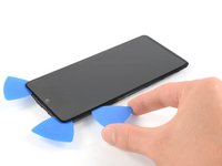
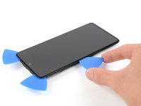
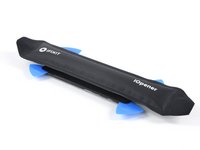
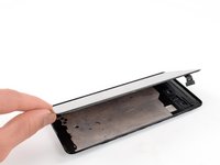
Prepare an iOpener and apply it to the display for at least two minutes to loosen the adhesive beneath.
-
-
-
Bu adımda kullanılan alet:Plastic Cards$2.99
-
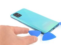
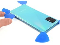
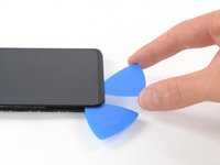
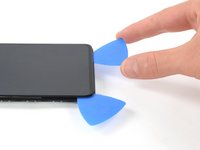
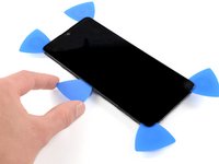
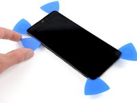
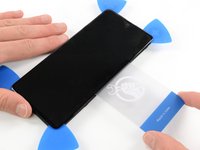
Insert a plastic card on the left edge into the gap between display and the phone assembly.
-
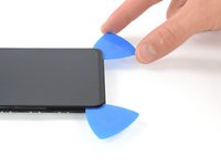
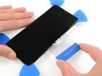
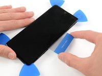
Press the plastic card in and slide it back and forth until you cut through the entire adhesive.
-
Once you are sure you cut through the adhesive, remove the four opening picks from the corners.
-
-
-
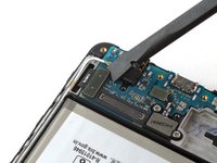
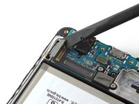
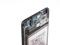
Use a spudger to disconnect the main board connector from the rear side of the PCB.
-
-
-
Use the flat side of the spudger to unglue the microphone from its compartment. Be careful not to break the flex part.
-
-
-
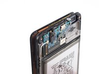
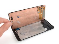
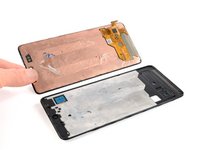
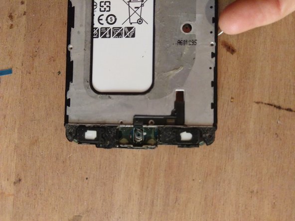
Peel off the PCB from its compartment and lift it to the other side without pulling.
-
Proceed element by element, trying not to break the flex parts. Here you’ll notice I broke the flex surrounding the jack port.
-
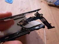
Take care not to damage/disconnect the two flex cables connected to the buttons at each end of the PCB (circled in red on the photo)
-
-
-
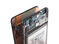
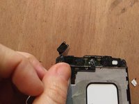
Remove or raise the glass on the other side of the phone.
-
Peel off the two button connectors.
-
-
-
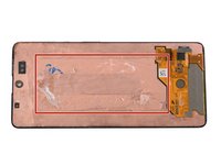
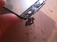
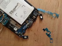
This is a view of the entire replacement board.
-
Note the flex parts circled in yellow on the photo: those are the most fragile parts of the PCB.
-
-
-
Place the new USB board in its casing
-
Plug the connector to the main board, below said board
-
-
-
Remove stickers from glued parts on new board
-
Remove the previous while filtering sticker under the buttons
-
Glue both backlight elements into their casing
-
-
-
At this point, there are 17 screws to be reassembled at the back of the phone
-
Glue screen and back cover back in place
-


Follow the instructions in reverse order to assemble the device.
Follow the instructions in reverse order to assemble the device.
İptal et: Bu kılavuzu tamamlamadım.
3 farklı kişi bu kılavuzu tamamladı.
Bu çevirmenlere özel teşekkürler:
100%


Bu çevirmenler dünyayı onarmamıza yardım ediyor! Katkıda bulunmak ister misiniz?
Çeviriye Başlayın ›

2Kılavuz Yorumları
The tutorial is not accurate, because from step 20 phone model in photos is A510F (A5 2016) not A515 (A51 2019) , it has different shape PCB
Thanks, I got confused between the shortened model names, I fixed the category.