Bu sürüm, hatalı düzenlemeler içerebilir. En son doğrulanmış bellek kopyası dönün.
Neye ihtiyacın var
-
Bu adım çevrilmemiş. Çevrilmesine yardım edin
-
Insert a SIM card eject tool, bit, or a straightened paperclip into the hole on the SIM tray, located at the top edge of the phone next to the plastic antenna band.
-
Press in firmly to eject the tray.
-
-
Bu adım çevrilmemiş. Çevrilmesine yardım edin
-
Heat an iOpener and apply it to the back cover's bottom edge for two minutes.
-
-
Bu adım çevrilmemiş. Çevrilmesine yardım edin
-
Apply a suction cup to the back of the phone, as close to the center of the bottom edge as possible.
-
Pull on the suction cup with strong, steady force to create a gap between the back cover and the frame.
-
Insert the point of an opening pick into the gap.
-
-
Bu adım çevrilmemiş. Çevrilmesine yardım edin
-
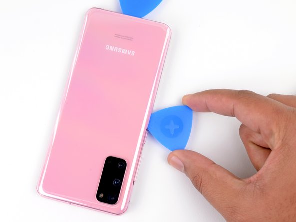
Slide the pick back and forth along the bottom edge to slice through the adhesive.
-
Leave your opening pick in the seam to prevent the adhesive from resealing.
-
-
Bu adım çevrilmemiş. Çevrilmesine yardım edin
-
Apply a heated iOpener to the left edge of the back cover for two minutes.
-
-
Bu adım çevrilmemiş. Çevrilmesine yardım edin
-
Apply a suction cup to the back of the phone, as close to the center of the left edge as possible.
-
Pull on the suction cup with strong, steady force to create a gap between the back cover and the frame.
-
Insert the point of an opening pick into the gap.
-
You can try also applying a few drops of high concentration (over 90%) isopropyl alcohol into the seam to help loosen the adhesive.
-
-
Bu adım çevrilmemiş. Çevrilmesine yardım edin
-
Once the pick is underneath the glass's edge, tilt it downward and insert it further to fully separate the back cover's adhesive.
-
-
Bu adım çevrilmemiş. Çevrilmesine yardım edin
-
Slide the pick all along the left edge of the phone to separate the back cover's adhesive.
-
Leave your pick under the left edge of the glass near the top left corner to prevent the adhesive from resealing.
-
-
Bu adım çevrilmemiş. Çevrilmesine yardım edin
-
Apply a heated iOpener to the right edge of the back cover for two minutes.
-
-
Bu adım çevrilmemiş. Çevrilmesine yardım edin
-
Apply a suction cup to the back of the phone, as close to the center of the right edge as possible.
-
Pull on the suction cup with strong, steady force to create a gap between the back cover and the frame.
-
Insert the point of an opening pick into the gap.
-
-
Bu adım çevrilmemiş. Çevrilmesine yardım edin
-
Slide the pick all along the right edge of the phone to separate the back cover's adhesive.
-
Leave your pick under the right edge of the glass near the top of the device to prevent the adhesive from resealing.
-
-
-
Bu adım çevrilmemiş. Çevrilmesine yardım edin
-
Apply a heated iOpener to the top edge of the back cover for two minutes.
-
-
Bu adım çevrilmemiş. Çevrilmesine yardım edin
-
Gradually slide the pick from the right edge of the device around the top right corner.
-
Continue slicing along the top edge all the way to the top left corner to fully separate the back cover adhesive.
-
-
Bu adım çevrilmemiş. Çevrilmesine yardım edin
-
Lift the back cover slowly. Use opening picks to slice any remaining adhesive.
-
Remove the back cover.
-
This is a good point to power on your phone and test all functions before sealing it up. Be sure to power your phone back down completely before you continue working.
-
Remove any adhesive chunks with a pair of tweezers or your fingers. Apply heat if you're having trouble separating the adhesive.
-
If you're using Samsung custom-cut adhesives, follow this guide.
-
If you're using double-sided tape, follow this guide.
-
-
Bu adım çevrilmemiş. Çevrilmesine yardım edin
-
Use a Phillips #00 screwdriver to remove the five 4 mm-long screws securing the motherboard bracket.
-
-
Bu adım çevrilmemiş. Çevrilmesine yardım edin
-
Use a pair of tweezers to gently pull up and unclip the motherboard bracket from the plastic midframe.
-
-
Bu adım çevrilmemiş. Çevrilmesine yardım edin
-
Gently peel the wireless charging coil away from the device.
-
Remove the wireless charging coil.
-
-
Bu adım çevrilmemiş. Çevrilmesine yardım edin
-
Use a spudger to pry up and disconnect the battery connector.
-
-
Bu adım çevrilmemiş. Çevrilmesine yardım edin
-
Use a Phillips #00 screwdriver to remove the five 4 mm-long screws securing the loudspeaker and lower midframe.
-
-
Bu adım çevrilmemiş. Çevrilmesine yardım edin
-
Insert the point of a spudger or a pair of tweezers into the notch in the top left corner of the midframe and pry up to release the clips holding it in place.
-
Remove the loudspeaker and lower midframe.
-
-
Bu adım çevrilmemiş. Çevrilmesine yardım edin
-
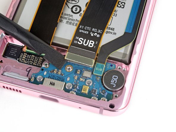
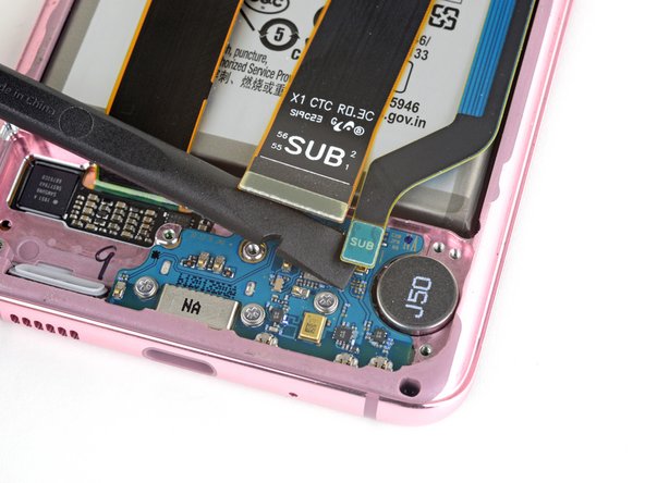
Use a spudger to pry up and disconnect the main and auxiliary flex cables from the daughterboard near the bottom of the device.
-
-
Bu adım çevrilmemiş. Çevrilmesine yardım edin
-
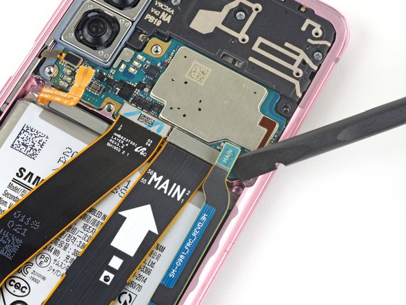
Use a spudger to pry up and disconnect the main and auxiliary flex cables from the motherboard.
-
-
Bu adım çevrilmemiş. Çevrilmesine yardım edin
-
Gently peel up and remove the main and auxiliary flex cables.
-
-
Bu adım çevrilmemiş. Çevrilmesine yardım edin
-
Use a spudger to pry up and disconnect the main display flex cable from the motherboard.
-
-
Bu adım çevrilmemiş. Çevrilmesine yardım edin
-
Gently peel up and bend the display flex cable out of the way of the motherboard and battery.
-
-
Bu adım çevrilmemiş. Çevrilmesine yardım edin
-
Use a Phillips #00 screwdriver to remove the four 4 mm-long screws securing the upper midframe.
-
-
Bu adım çevrilmemiş. Çevrilmesine yardım edin
-
Insert the point of a spudger into the notch on the right side of the upper midframe and pry up to release the clips holding it into place.
-
Remove the upper midframe.
-
-
Bu adım çevrilmemiş. Çevrilmesine yardım edin
-
Use a spudger to pry up and disconnect the side button flex cable from the motherboard.
-
Use a pair of tweezers to bend the cable out of the way of the motherboard.
-
-
Bu adım çevrilmemiş. Çevrilmesine yardım edin
-
Pry up and disconnect the front facing camera flex cable from the motherboard.
-
Bend the cable out of the way of the motherboard.
-
-
Bu adım çevrilmemiş. Çevrilmesine yardım edin
-
Pry up and disconnect the front-facing sensor array cable from the motherboard.
-
Bend the cable out of the way of the motherboard.
-
-
Bu adım çevrilmemiş. Çevrilmesine yardım edin
-
Use a Phillips #00 screwdriver to remove the two screws securing the motherboard and camera assembly.
-
One 4 mm-long screw
-
One 3 mm-long screw
-
-
Bu adım çevrilmemiş. Çevrilmesine yardım edin
-
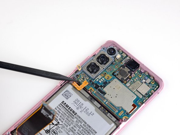
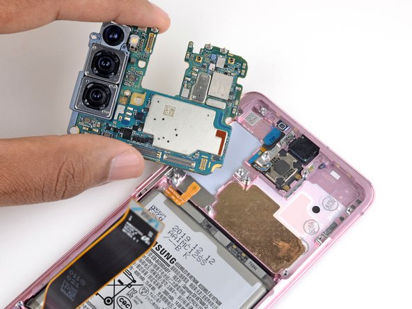
Insert the flat end of a spudger into the bottom left corner of the motherboard assembly and pry up to release it from the phone body.
-
Remove the motherboard assembly.
-
-
Bu adım çevrilmemiş. Çevrilmesine yardım edin
-
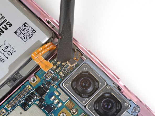
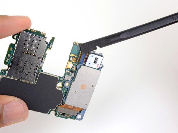
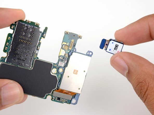
Use the flat end of a spudger to pry up and disconnect the ultrawide camera connector from the motherboard.
-
Remove the ultrawide camera module.
-
-
Bu adım çevrilmemiş. Çevrilmesine yardım edin
-
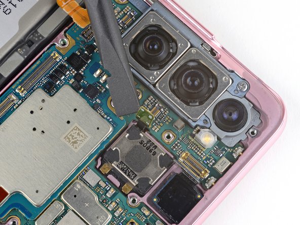
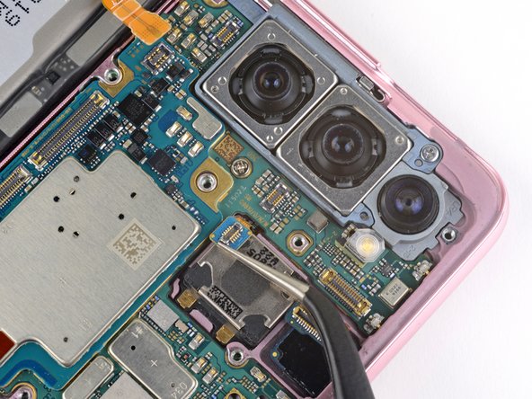
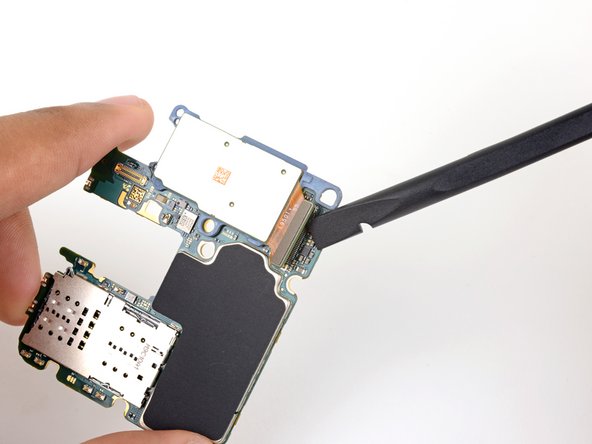
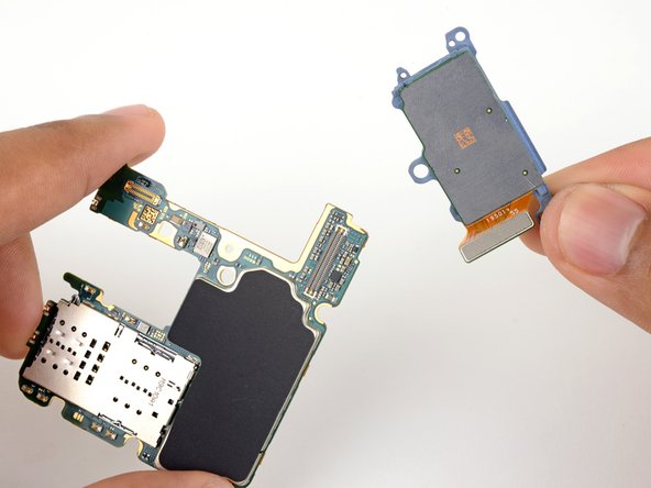
Use a spudger to pry up and disconnect the telephoto and wide-angle camera connector from the motherboard.
-
Remove the remaining rear facing camera module.
-