Giriş
This guide will show you the steps to removing and replacing the motherboard of the camera.
Neye ihtiyacın var
-
-
Place the device so bottom of the camera is facing up .
-
Remove the five black M1.4 X 3.5 Phillips head screws with a Phillips #000 screwdriver.
-
-
-
Remove the marked screw with a Phillips #000 screwdriver.
There is another screw under the “multi” cover that I think has to be removed to remove the button board
And another screw on the inner left side to remove the left cover
I struggled for about 3/4hr to get that cover off before finding that screw just after I replaced everything and packed up for the night. I took a photo, but there doesn’t seem to be a way to post it.
-
-
-
Use the plastic opening tool to remove the button board.
The tutorial would have been more useful if the photo had shown HOW to use the plastic opening tool, which side of the tool must be used, and where to put it. Maybe a comment given as an answer could explain it.
There is an extra screm hidden under the multi/charger-cover! Very important to know.: :)
-
-
-
-
Use the plastic opening tool with a prying motion to remove the side cover of the camera.
-
-
-
Orient the device so the lens is facing down.
-
Remove the two black M1.4 X 3.5 Phillips head screws using Phillips #000 screwdriver.
-
-
-
Orient the device so the lens is facing down.
-
Remove the black M1.4 X 3.5 Phillips head screw.
Removing this screw behind the side cover should be done before removing the side cover of the camera, since this screw holds the cover !
This screw has to be removed before, in order to remove the left cover. Then to remove the back with the display also two other screws, one on the lef and another on the right side, under the already removed covers have to be removed
-
-
-
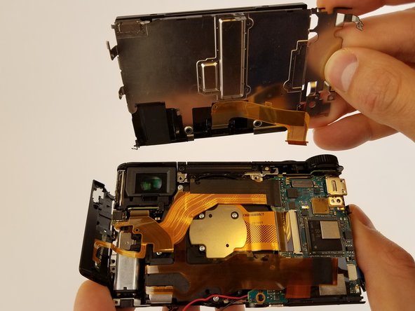
Make sure all ribbon cables are unplugged and remove the motherboard.
Achtung,
alle Buchsen der Flachbandkabel sind mit einer Verriegelung versehen, diese müssen vorsichtig von hinten zum Kabel hin aufgeklappt werden. Nach dem einstecken des Kabel die Verriegelung wird herunterdrücken, Wird die Verriegelung nicht gelöst wird die Steckbuchse beschädigt sodass die Hauptplatine ausgetauscht werden muss.
Detlev’s warning is important! — Danger! —
all the ribbon cable sockets are provided with a lock, which must be carefully opened from the rear towards the cable. After inserting the cable, the lock is pressed down. If the lock is not released, the socket will be damaged so that the main board must be replaced.
-


To reassemble your device, follow these instructions in reverse order.
To reassemble your device, follow these instructions in reverse order.
İptal et: Bu kılavuzu tamamlamadım.
Bir başkası bu kılavuzu tamamladı.
2Kılavuz Yorumları
super Anleitung, trotz aller Vorsicht ist ein Flachbandkabel kaputt gegangen, und zwar das 2 adrige zu Sucher. Wie kann man Flachbandkabel reparieren oder ersetzen?
LG
Michael
Hello!
Nice help to open the camera for fixing viewfinder problems: when not switching on, even when FINDER/MONITOR mode on FINDER, there might be a bad contact in the visor connector. It is a snap lock micro connector, open the lock, then carefully remove clean and replace ribbon cable:this may clear the trouble.
But attention: At least on HX9O without V ext. there are some more screws ;-) and niceties
- one in step 3, under the MULTI connector cap
- 3 on different places to remove LCD screen
Also, there is also an antenna , connected to the LCD assembly and lightly glued on the side