Giriş
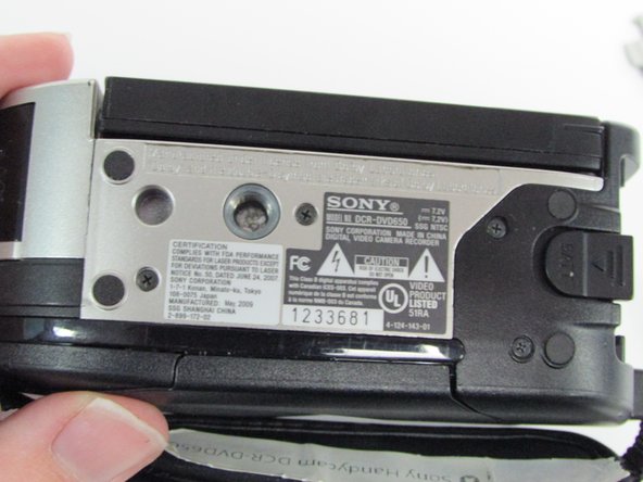
This guide shows you how to replace the optical assembly of the device. The optical assembly includes the Carl Zeiss Lens. With this device powered on, you will be able to look through the viewfinder or watch via the LCD screen to see the world that your lens is capturing. Do your best to avoid touching the lens and if you do, remember to clean off your fingerprints later.
Neye ihtiyacın var
-
-
The hand strap can become a hindrance at times. It's best to begin by unlatching it.
-
On the padded section of the hand strap, pry up the Velcro and peel out the thin strap sandwiched between them.
-
Push the thin strap through the metal loop at the front of the device.
-
The strap will still be connected at one end to the device, but will be able to be moved out of the way to provide a more stable working surface.
-
-
-
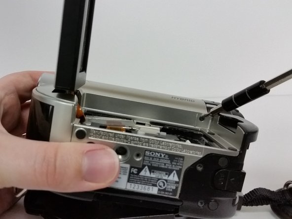
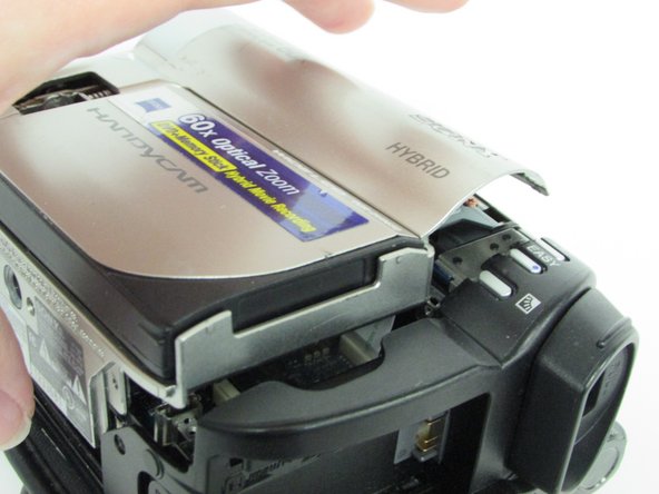
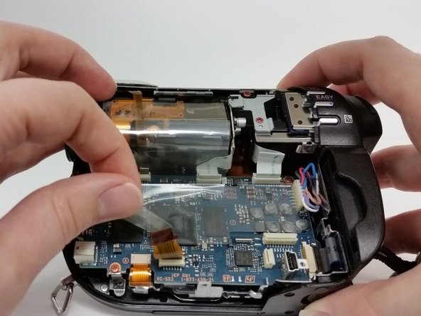
Once the silver cover is pried up, slip the piece out to the right.
-
There are two cables attached to the board beneath that need to be disconnected.
-
Disconnect both of the no-fuss ribbon cables.
-
Use your fingernails or a pair of tweezers to pull on the tabs on either side of the ribbon cable to remove.
-
Remove the other cable by pulling up on the cable itself.
-
-
-
-
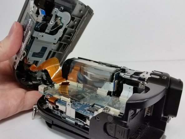
Once the device is open, carefully remove the no-fuss ribbon cable from the motherboard and set aside the silver portion of the device.
-
There may be a piece of plastic adhesive shielding the motherboard. Remove gently, being careful not to pull on the ribbon cables beneath it, and set aside.
-
-
-
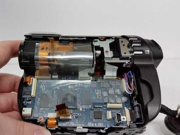
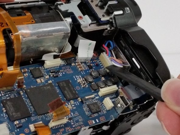
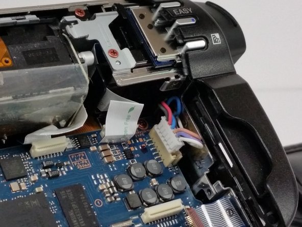
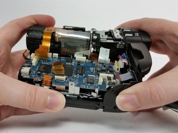
Locate all of the cables attached to the motherboard.
-
Carefully disconnect all cables.
-
There are four orange no-fuss ribbon connectors. To disconnect these cables pull up on the tabs protruding from both sides of the cable rather than pulling on the cable itself.
-
There are two white no-fuss ribbon cable connectors. To disconnect these cables, pull them straight out of the connector.
-
In the lower corner on the far right, disconnect the Zero-Insertion Force (ZIF) connector by flipping up the small black bar before removing the cable.
-
-
-
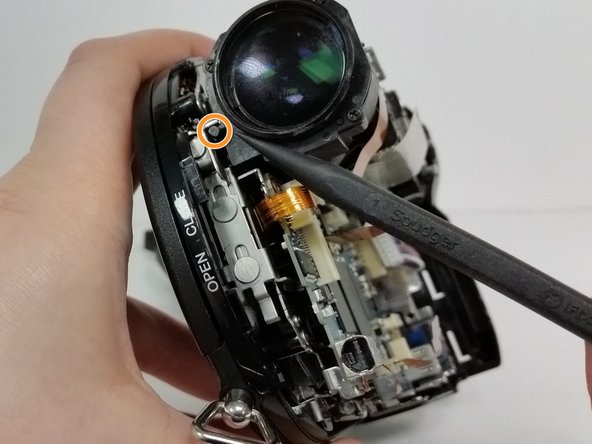
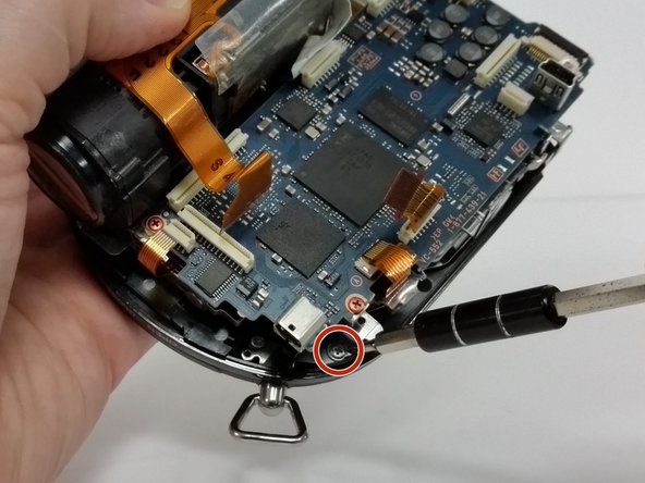
Now that all of the cables are disconnected, remove the two bronze screws (2mm, Phillips #00) on the lens housing.
-
Next we'll need to remove some screws from inside the disc housing.
-
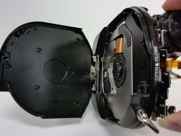
If the disc door has closed at some point, turn the camcorder lens toward you and locate a small cylindrical lever to the left of the lens.
-
Pushing down on this lever will manually release the door.
-
-
-
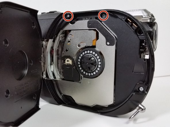
Remove the top two upper screws (4mm, Phillips #00) on the interior of the DVD housing.
-
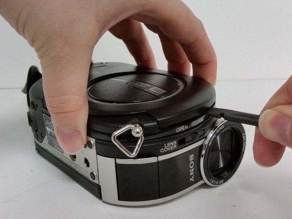
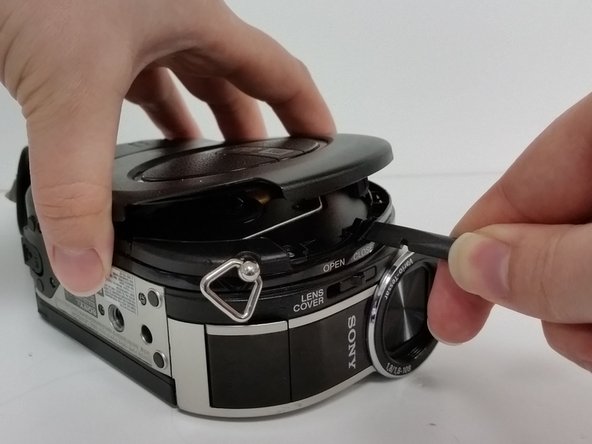
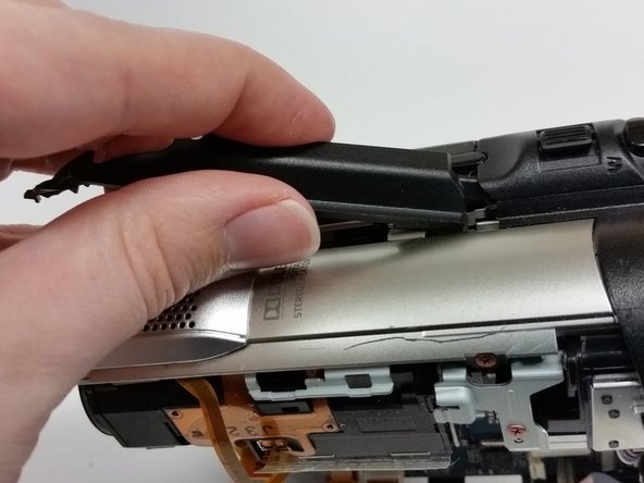
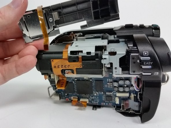
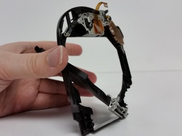
Pry up the black strip of housing between the open slider and the remaining silver housing above the lens.
-
A bit of a gentle tug and wiggle of the piece towards the lens side of the device, should allow you to completely remove the piece.
-
-
-
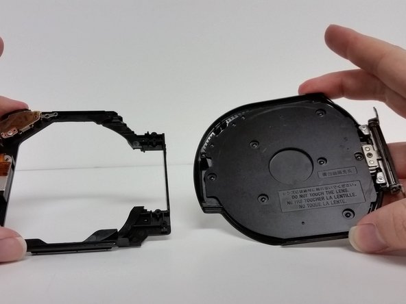
After the door is separated from the frame, set the door aside.
-
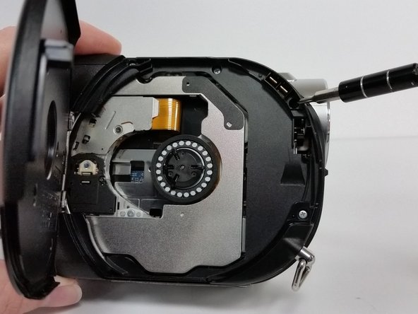
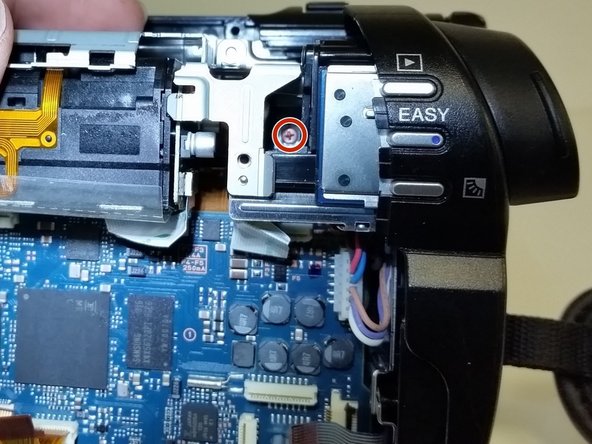
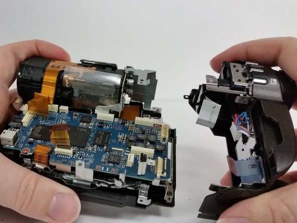
Remove the two bronze (2mm, Phillips #00) screws at the top of the metal frame.
-
Separate the disc reading frame from the optical housing frame and set the disc reading frame aside.
-
-
-
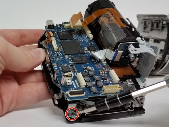
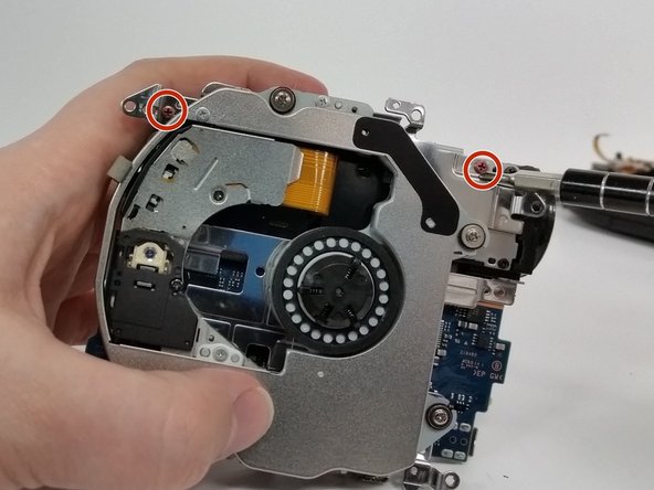
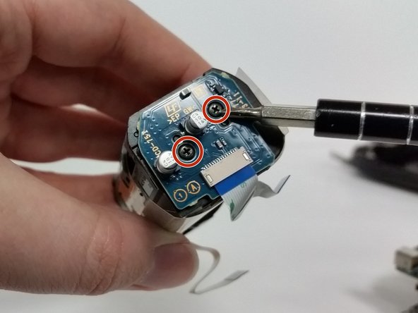
You've reached the optical assembly.
-
Depending on the part you've received to replace the optical assembly, you may need to remove the circuit panel on the back of the assembly.
-
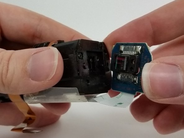
Unscrew the two screws (5mm, Phillips #00) from the circuit board and separate the board from the assembly.
-


To reassemble your device, follow these instructions in reverse order.
To reassemble your device, follow these instructions in reverse order.

Ekip

University of Illinois Urbana-Champaign, Team 1-2, Scrogum Spring 2017 University of Illinois Urbana-Champaign, Team 1-2, Scrogum Spring 2017 üyesi
UICU-SCROGUM-S17S1G2
1 Üye
5 adet Kılavuz yazıldı