Bu sürüm, hatalı düzenlemeler içerebilir. En son doğrulanmış bellek kopyası dönün.
Neye ihtiyacın var
-
Bu adım çevrilmemiş. Çevrilmesine yardım edin
-
Remove the two Pentalobe screws next to the lightning port connector using a pentalobe screwdriver.
-
2x 3.6mm Pentalobe Screws
-
-
Bu adım çevrilmemiş. Çevrilmesine yardım edin
-
Place a suction cup over the screen, just above the home button and gently lift up.
-
NOTE: If the screen is shattered, use 2-3 pieces of packing tape over the shattered glass to form a proper seal.
-
Please note the in the lower left corner of the display, the iPhone has a cutout that is made to help removing the display assembly from the frame. It is located directly above the audio jack port.
-
-
Bu adım çevrilmemiş. Çevrilmesine yardım edin
-
CAUTION: Do not try to completely remove the display assembly from the frame! There are three flex cables still attached to the top of the iPhone, and removing the display at this stage can destroy them.
-
Once the clips have been release on the bottom and sides of the display assembly, lift the bottom of the display assembly up away from the rear case until about a 90-degree angle.
-
-
Bu adım çevrilmemiş. Çevrilmesine yardım edin
-
Note: While disconnecting the battery, you will have to hold the Display assembly upward with one hand, while removing the screws and retaining plate with the other hands.
-
Remove three Phillips screws:
-
1x 1.8 mm Phillips Screw 1x 1.6 mm Phillips screw and 1x 1.2 mm Phillips screws
-
Be careful to only pry up the battery connector and not to pry up the socket on the logic board. If you pry up on the logic board socket, you may break the connector entirely.
-
-
Bu adım çevrilmemiş. Çevrilmesine yardım edin
-
Remove the three Phillips screws securing the EMI shield to the logic board. ( The upper right screw is an aluminum screw which makes it non-magnetic. )
-
Two 1.2mm Phillips Screws
-
1x 1.6mm Phillips non-magnetic Phillips Screws
-
In order to remove the EMI shield, slightly lift it upward at an angle using tweezers, then slide the EMI shield toward the battery and remove it.
-
-
-
Bu adım çevrilmemiş. Çevrilmesine yardım edin
-
Use the pointed end of the nylon spudger tool to disconnect the 3x front panel assembly cables:
-
1) Front-Facing Camera/Accessory Cable
-
2) LCD Flex Cable
-
Note: The digitizer cable is underneath the LCD flex cable as shown on next slide.
-
-
Bu adım çevrilmemiş. Çevrilmesine yardım edin
-
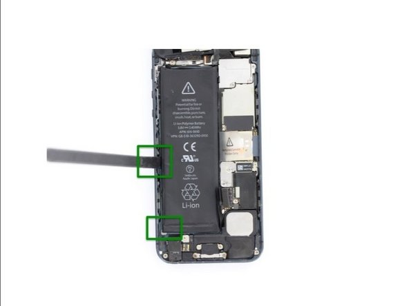
Gently pull the battery pull-tab ti remove the battery from the frame.
-
NOTE: The battery is held in place with adhesive, Heat the back of the frame a little bit and use a nylon spludger to help you lift the battery off the frame.
-
Safe Area to pull are marked in GREEN.
-
If you haven't already done it at this point, remove the sim card tray from the iPhone as well.
-
-
Bu adım çevrilmemiş. Çevrilmesine yardım edin
-
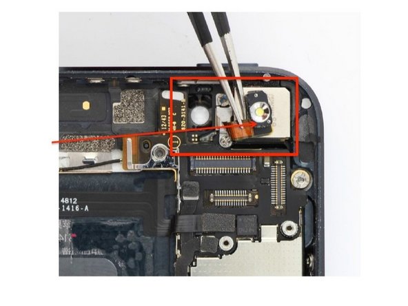
Starting at the top of the phone, remove the two Phillips screws holding the camera flash retaining plate.
-
1x 1.5mm Phillips Srew (RED)
-
1x 2.3mm Phillips Screw ( Green)
-
Use tweezers to carefully fold the flash flex cable upward.
-
NOTE: The metal box that the flash module rests in will usually stay adhered to the cable. Should they separate, set aside the metal housing for later installation.
-
-
Bu adım çevrilmemiş. Çevrilmesine yardım edin
-
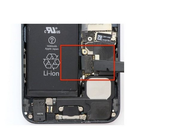
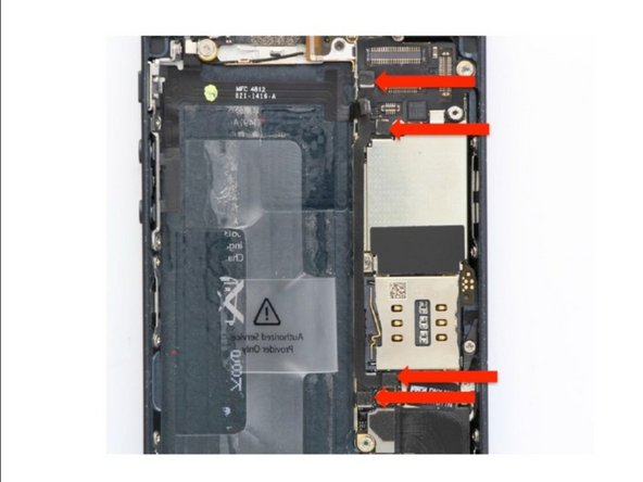
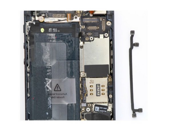
Start by disconnecting the power/audio control cable from the logic board.
-
Then, Go after the inter-connect cable boards using the pointed end of a spludger.
-
Note: the inter-connect cables are stuck together with an adhesive. It's normal if they separate during removal. The straight cable is for cellular diversity, which, if faulty, impacts cellular reception and download speeds. The cable with two curves is for GPS. Without this cable, navigation will not work.
-
-
Bu adım çevrilmemiş. Çevrilmesine yardım edin
-
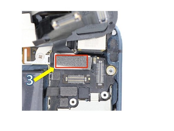
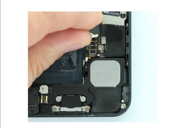
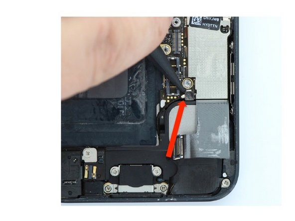
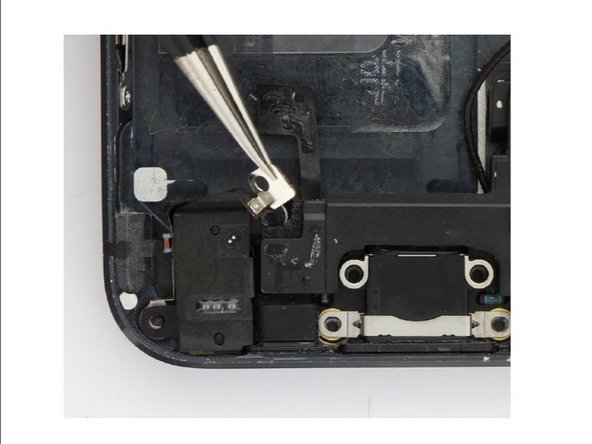
Disconnect the dock connector cable connector from the board using the pointed end of the nylon spudger as shown.
-
Peel the dock connector cable from the logic board.
-
Disconnect the cellular service antenna using the pointed end of the nylon spudger under the metal clasp.
-
-
Bu adım çevrilmemiş. Çevrilmesine yardım edin
-
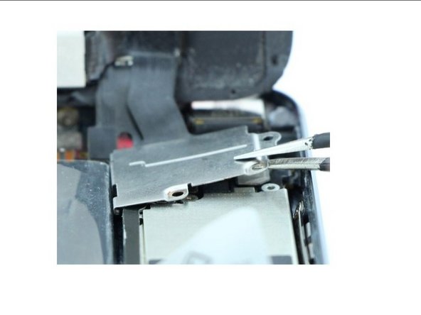
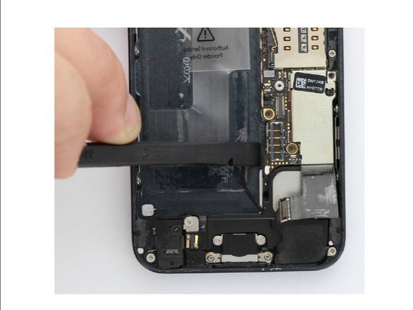
At the top of the frame, remove the two 1.3mm Phillips screws holding the cellular service and GPS antenna's against the frame.
-
-
Bu adım çevrilmemiş. Çevrilmesine yardım edin
-
Remove the logic board screw.
-
2x 2.8mm standoff screws. ( RED)
-
2x 2.3mm Phillips screws. (BLUE)
-
One 2.6mm standoff screw.
-
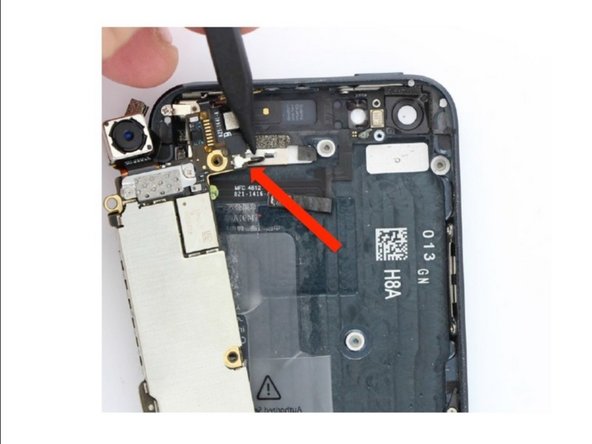
CAUTION: Do not pull the logic board out! The Wi-Fi antenna is connected to the underside of the logic board. Use the flat end of the nylon spudger to gently lift the lower end of the logic board, enough to grip for removal.
-
Once done, roll the logic board over and disconnect the Wi-Fi antenna using the pointed end of the nylon spudger from under the antenna's clasp.
-
-
Bu adım çevrilmemiş. Çevrilmesine yardım edin
-
Remove the following screws that secure the dock connector, headphone jack, and loud speaker into the frame.
-
One 2.5 mm Phillips Screw (red)
-
Two 3.3 mm Phillips screws (blue)
-
One 2.9 mm Phillips Screw (yellow)
-
Two 1.5mmPhillips screws (green)
-
One 2.8 mm Phillips screw (cyan)
-
Peel both the home button connector and audio jack filter ground from the loud speaker.
-
-
Bu adım çevrilmemiş. Çevrilmesine yardım edin
-
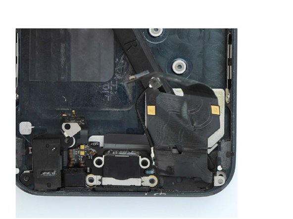
Remove the loud speaker from the frame.
-
Peel back the dock connector cable from the frame.
-
Dot not loose the four spring washers underneath the lightning port housing.
-
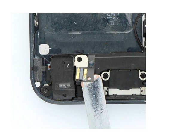
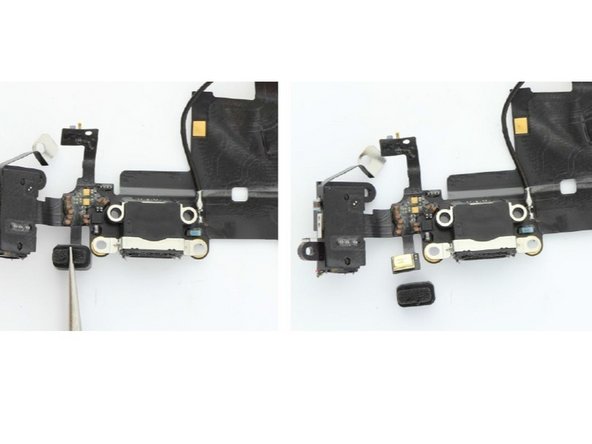
Pull the rubber boot off the lower microphone area of the dock connector cable.
-
Carefully peel the headphone jack filter off the headphone jack housing.
-
-
Bu adım çevrilmemiş. Çevrilmesine yardım edin
-
NOTE: BE CAREFUL not to rip or tear the filter!
-
Be sure to transfer all foams pad to the new dock connector assembly if necessary. Good luck ! :)
-


İptal et: Bu kılavuzu tamamlamadım.
9 farklı kişi bu kılavuzu tamamladı.

Ekip
