Bu sürüm, hatalı düzenlemeler içerebilir. En son doğrulanmış bellek kopyası dönün.
Neye ihtiyacın var
-
Bu adım çevrilmemiş. Çevrilmesine yardım edin
-
Remove the two 3.4 mm P2 Pentalobe screws on the bottom edge of the iPhone, on either side of the Lightning connector.
-
-
-
Eğer iSclack'in üzerindeki plastik derinlik ölçer, iSclack'in merkezine bitişik ise, çıkarın—iPhone 6 gibi büyük telefonlarda kullanılmasına gerek yoktur.
-
Vakumlu ağızları aralamak için iSclack'in sapını kapatın.
-
-
-
iPhone'unuzun altını vakumlu ağızların arasına yerleştirin.
-
iSclack'in üstteki vakumlu ağzını, ana sayfa düğmesini kapatmayacak ancak ana sayfa düğmesinin hemen yukarsına yerleşecek şekilde ekranın üzerine getirin.
-
iSclack'in ağzını kapatmak için sapı açın. Vakumlu ağızları ortalayarak yerleştirip, telefonun ön ve arkasına doğru sıkıca bastırın.
-
-
Bu adım çevrilmemiş. Çevrilmesine yardım edin
-
If you don't have an Anti-Clamp, follow the next three steps to use a suction handle.
-
Apply mild heat to the lower edge of the iPhone using an iOpener or hair dryer for about a minute.
-
-
Bu adım çevrilmemiş. Çevrilmesine yardım edin
-
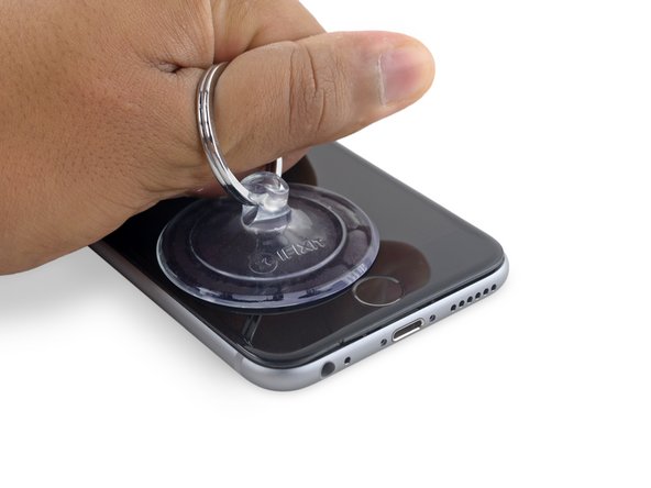
Apply a suction cup to the lower left corner of the display assembly.
-
Take care not to place the suction cup over the home button.
-
-
Bu adım çevrilmemiş. Çevrilmesine yardım edin
-
Pull up on the suction cup with firm, constant pressure to create a slight gap between the front panel and rear case.
-
-
Bu adım çevrilmemiş. Çevrilmesine yardım edin
-
Place the flat edge of a spudger into the gap between the screen and rear case, directly above the headphone jack.
-
-
Bu adım çevrilmemiş. Çevrilmesine yardım edin
-
Twist the spudger to widen the gap between the front panel assembly and the rest of the phone.
-
-
Bu adım çevrilmemiş. Çevrilmesine yardım edin
-
Insert the flat end of the spudger on the left side of the phone, between the display assembly and rear case.
-
Slide the spudger up the side of the phone to separate the adhesive and pop the clips free.
-
-
Bu adım çevrilmemiş. Çevrilmesine yardım edin
-
Remove the spudger and reinsert it on the bottom edge, where you pried the phone open.
-
Slide the spudger to the right, along the bottom edge of the phone.
-
-
Bu adım çevrilmemiş. Çevrilmesine yardım edin
-
Slide the spudger up the right side to continue separating the adhesive and popping the display clips free from the iPhone.
-
-
Bu adım çevrilmemiş. Çevrilmesine yardım edin
-
Use the suction cup to open the display, breaking the last of the adhesive.
-
-
Bu adım çevrilmemiş. Çevrilmesine yardım edin
-
Pull up on the nub on the top side of the suction cup to remove it from the front panel.
-
-
Bu adım çevrilmemiş. Çevrilmesine yardım edin
-
Gently grasp the display assembly and lift it up to open the phone, using the clips at the top of the front panel as a hinge.
-
Open the display to about a 90º angle, and lean it against something to keep it propped up while you're working on the phone.
-
Add a rubber band to keep the display securely in place while you work. This prevents undue strain on the display cables.
-
-
Bu adım çevrilmemiş. Çevrilmesine yardım edin
-
Remove two Phillips screws securing the battery connector bracket, of the following lengths:
-
One 2.9 mm screw
-
One 2.2 mm screw
-
-
-
Bu adım çevrilmemiş. Çevrilmesine yardım edin
-
Use the point of a spudger to disconnect the battery connector by prying it straight up from the logic board.
-
-
Bu adım çevrilmemiş. Çevrilmesine yardım edin
-
Push the battery connector away from the logic board until it stays separated from its socket, so as to avoid any accidental connection to the battery while you work.
-
-
Bu adım çevrilmemiş. Çevrilmesine yardım edin
-
Remove the following four Phillips screws securing the display cable bracket:
-
Three 1.2 mm screws
-
One 2.8 mm screw
-
-
Bu adım çevrilmemiş. Çevrilmesine yardım edin
-
Use a spudger or a clean fingernail to disconnect the front camera flex cable by prying it straight up from its socket on the logic board.
-
-
Bu adım çevrilmemiş. Çevrilmesine yardım edin
-
Disconnect the digitizer cable by prying it straight up from its socket on the logic board.
-
-
Bu adım çevrilmemiş. Çevrilmesine yardım edin
-
Disconnect the display cable by prying it straight up from its socket on the logic board.
-
-
Bu adım çevrilmemiş. Çevrilmesine yardım edin
-
Use the flat end of a spudger to disconnect the rear camera from its socket on the logic board.
-
-
Bu adım çevrilmemiş. Çevrilmesine yardım edin
-
Remove the following two Phillips screws over the rear camera bracket:
-
One 1.6 mm screw
-
One 2.0 mm screw
-
-
Bu adım çevrilmemiş. Çevrilmesine yardım edin
-
Insert a spudger to the side of the camera, between the rear case and the camera module.
-
Gently pry up on the camera to nudge it out from its housing.
-
-
Bu adım çevrilmemiş. Çevrilmesine yardım edin
-
Insert a SIM card eject tool or a paperclip into the small hole in the SIM card tray.
-
Press to eject the tray.
-
-
Bu adım çevrilmemiş. Çevrilmesine yardım edin
-
Remove the two 2.3 mm Phillips screws securing the upper component cable connector bracket.
-
-
Bu adım çevrilmemiş. Çevrilmesine yardım edin
-
Remove the following five Phillips screws securing the top left Wi-Fi antenna:
-
Two 1.5mm screws
-
One 2.3 mm screw
-
One 1.9 mm screw
-
One 2.0 mm screw
-
-
Bu adım çevrilmemiş. Çevrilmesine yardım edin
-
Use the flat end of a spudger to disconnect the audio control cable from its socket on the logic board.
-
-
Bu adım çevrilmemiş. Çevrilmesine yardım edin
-
Use the pointed tip of a spudger to disconnect the antenna cable from its socket on the upper right corner of the logic board.
-
-
Bu adım çevrilmemiş. Çevrilmesine yardım edin
-
Use the pointed tip of a spudger to disconnect the antenna cable from its socket on the lower left corner of the logic board.
-
-
Bu adım çevrilmemiş. Çevrilmesine yardım edin
-
Insert the flat end of a spudger underneath the Lightning connector ribbon cable. Lift up to disconnect it from its socket on the logic board.
-
-
Bu adım çevrilmemiş. Çevrilmesine yardım edin
-
Gently pull up on the antenna cable to de-route it from the two clips on the right side of the logic board.
-
-
Bu adım çevrilmemiş. Çevrilmesine yardım edin
-
Remove the 1.3 mm Phillips screw securing the NFC bracket to the logic board.
-
-
Bu adım çevrilmemiş. Çevrilmesine yardım edin
-
Remove the following two Phillips screws:
-
One 2.5 mm screw at the top of the logic board
-
One 1.4 mm screw set into the upper edge of the rear case
-
-
Bu adım çevrilmemiş. Çevrilmesine yardım edin
-
Remove the final three screws securing the logic board to the rear case:
-
One 1.9 mm Phillips screw
-
One 2.5 mm hex nut
-
One 1.8 mm Phillips screw
-
-
Bu adım çevrilmemiş. Çevrilmesine yardım edin
-
Insert an opening pick below the lower edge of the logic board, between the board and the loudspeaker.
-
Use the opening pick to gently lift the logic board out of its housing.
-
Remove the logic board.
-


İptal et: Bu kılavuzu tamamlamadım.
224 farklı kişi bu kılavuzu tamamladı.

33 Yorum
So all the logic boards come with the components installs? Like the High band PAD, power amplifier avago, power amplifier Skyworks, power amplifier TriQuint, LTE modem Qualcomm, and lastly the Apps processor Apple SoC stacked on Elpida RAM. Here I thought you had to buy them.
I'm also assuming that some don't. I would like to know that alternative.
Yup! The SSD is a flash memory chip hidden underneath an EMI shield on the logic board. You can see it in our teardown.
Um, no, actually the NAND/ssd/flash/storage chip is the big Toshiba one in the middle, it’s the one next to the line of capacitors, and is not under the shields. there are shields on either side of it. Look at the teardown page you linked to yourself and you will confirm what I’ve said.
great guide worked perfectly, had some minor water damaged internals with a completely good logic board, replaced it in a 16g pos basically have a brand new 128g 6s