Ana içeriğe geç

Google Home Teardown

İngilizce
İtalyanca
Adım 6
Google Home Teardown: adım 0, 3 resimden 1. Google Home Teardown: adım 0, 3 resimden 2. Google Home Teardown: adım 0, 3 resimden 3.
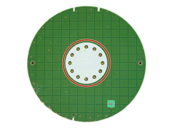
  • Here's the source of our board removal strife: A layer of super sticky adhesive, keeping the capacitive board in contact with the plastic upper case.

  • This round green grid is half of an array of capacitors—with the other half buried in another, deeper PCB layer. By measuring the total capacitance of each row and column, the controller can detect when—and pinpoint where—your finger is modifying the capacity of the grid through capacitative coupling. Science!

  • This side of the board also hosts an array of 12 status LEDs.

  • On the backside we find some chips:

  • Atmel ATSAMD21 32-bit ARM Cortex-M0+ microcontroller

  • Two NXP PCA9956BTW LED drivers

  • Two InvenSense INMP621 MEMS microphones—will only two be enough compared to the Echo's seven?

  • Ambient Light Sensor

Çeviri buraya girin

Çeviri buraya girin

Çeviri buraya girin

Çeviri buraya girin

Çeviri buraya girin

Çeviri buraya girin

Çeviri buraya girin

Çeviri buraya girin

Katkılarınız, açık kaynak Creative Commons lisansı altında lisanslanmaktadır.