
Bu, bir LCD TV'nin içindeki en yaygın bulunan kartları açıklayan genel bir Wiki'dir. Kartlar çoğu TV'de ortaktır ancak kartların varyasyonlarına sahip olabilen veya daha fazla işlev için ek kartlar eklenmiş üreticiler ve modeller mevcuttur. Bunlar, ilgili modelin servis kılavuzu kullanılarak değerlendirilmelidir.
Bir LCD TV nasıl çalışır?
TV bir AC kaynağına bağlanıp açıldığında, TV güç kaynağı kartı AC voltaj girişini alır. Buradan güç kaynağı kartı 5V Bekleme Voltajını (5VSTB) üretir ve Ana karta gönderir. Bu aşamada 5VSTB dışında başka bir voltaj olmayacaktır.
Ana Kart güç kaynağı kartından 5V bekleme voltajını aldığında, 3.3V voltaj üretmek için bir voltaj regülatörü entegresinden (IC) veya DC-DC devresinden geçirilir. 3.3V, MCU (mikrodenetleyici birimi) entegresine, CPU'ya ve Ön Panel kartına sağlanır. Artık bekleme LED ışığının yandığını görebiliriz ve TV artık Bekleme Modundadır.
Güç açma düğmesine bastıktan sonra, Ana kart güç kaynağı kartına Güç Açma sinyalini (PS_ON, PWR_ON vb. işaret kodu) gönderir. Bu PS_ON sinyali, Güç Kaynağı kartının PFC bölümüne ve ardından 24V, 12V, 5V, 3.3V vb. gibi diğer voltaj çıkışlarını Ana karta, T-con kartına ve (varsa) İnverter kartına/bölümüne üretmesi için PWM bölümüne gönderilir. Sonunda TV artık ekran görüntüsünü verebilir.
Bu Wiki için gösterim amacıyla bir Samsung LS32D85K kullanılmıştır. Bu modelin onarımı hakkında daha fazla bilgi burada bulunabilir Samsung LS32D85KTSR Power Supply Replacement
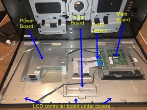
TV'nin arka paneli çıkarıldığında, her düz ekran TV türünün farklı bir parça seti olacaktır. LCD TV'ler genellikle şu devre kartlarını içerir:
- Ana Kart
- Güç Kaynağı Kartı
- T-Con Kartı
- LCD Panel Kontrol Kartları
- IR Sensörü
- Tuş Takımı Kontrolcüsü
Üreticiye ve modele bağlı olarak isteğe bağlı kartlar şunlardır:
- Arka Aydınlatma İnverter Kartı
- FRC Kartı
Arka kapak çıkarıldıktan sonraki ilk görünüm.
Güç kaynağı kartı nedir?
Bir güç kaynağının ne olduğunu tanımlayın ve muhtemelen 'ekipmanımı çalıştıran şebekeye takılı o kutu' gibi bir yanıt alırsınız. İşlev bu olsa da yaptığı şey çok karmaşıktır. Şebekeden gelen ham AC voltajını alır, normalde dünyadaki herhangi bir besleme voltajı ile uyumludur (toleransları, düşüşleri ve yükselmeleri ile birlikte) ve bunu kararlı, daha düşük bir DC voltajına dönüştürür. Giriş voltajındaki ve çıkış yük akımındaki değişikliklerle çıkış voltajını sabit tutmak için bir geri besleme döngüsü içerir.
Hızlı yük değişimlerine, tasarlanmış bir kontrol döngüsü tepki süresi içinde, minimum sonuçsal çıkış voltajı geçişleri ile tepki verilir. En yüksek standart şebeke voltajı için en yüksek yasal seviyede güvenlik yalıtımı sağlar ve tek bir bileşen arızasında bile minimum seviyede güvenli kalmaya devam eder. Yasal seviyelere kadar kontrollü yayılı ve iletilen gürültü emisyonlarına sahip olacak ve diğer kaynaklardan gelen gürültüye karşı bağışık olacaktır.
İyi bir tasarım, çıkış aşırı voltajına, birden fazla bileşen arızası zincirine, aşırı sıcaklıklara, elektrik çarpmasına veya hatta yangına neden olabilecek tekil dahili arızalara karşı çeşitli koruma seviyelerine sahip olacaktır.
Ana kart nedir?
Bazen anakart olarak da adlandırılan (bilgisayar anakartı ile karşılaştırma yapılır) Ana kart, ses ve video girişlerinin ve çıkışlarının bağlandığı devre kartıdır. Bu TV'nin beynidir ve genellikle dört ana işleve ayrılabilir:
1. CPU ve MCU (mikrodenetleyici birimi) işlemcileri aracılığıyla sistemi birden fazla sinyal yoluyla kontrol eder. Örneğin, güç kartına arka aydınlatmayı açmasını söyleyen; panele ne zaman açılıp kapanacağını söyleyen vb. Ana karttır.
2. HDMI, COAX, Component vb. gibi çok sayıda video konnektöründen de anlaşılacağı üzere, farklı türdeki video sinyali girişlerini işler. Bu video sinyallerini, daha sonra düz şerit LVDS kabloları aracılığıyla T-con kartına gönderilen RSDS tipi video sinyallerine dönüştüren Ana karttır.
3. Ana kart ayrıca ses entegresini de (hoparlörlerin bağlandığı ses yükselticiyi içerir) kapsar.
4. Ana kart geniş bir DC-DC bölümü içerir. Güç kaynağı kartından gücü aldıktan sonra sistemin geri kalanı için uygun voltajın belirlendiği yer burasıdır. Tuner voltajları, CPU ve GPU'nun yanı sıra RAM voltajı vb. buradan kontrol edilir. TV 3D veya Wi-Fi kapasitesine sahipse, Ana kart bu çevre birimlerinin de kontrolünü sağlayacaktır.
Bu çevirmenlere özel teşekkürler:
100%

Translation Bot dünyayı onarmamıza yardım ediyor! Katkıda bulunmak ister misiniz?
Çeviriye Başlayın ›
34 Yorum
اصلاح شاشة سمسونغ
fassihabdelghani - Yanıt Paylaş
i dont know if my main board is out are the black lights are out. i have a full picture under the black screen i use the flash light test and i have sound.
james pettit - Yanıt Paylaş
Then your problem is with your backlights. As with Christmas tree lights, they are connected in series, so when one goes out they all go out...
Paul Keates - Yanıt Paylaş
My sony TV turns off after 10 seconds and then the standby light blinks 6 times. I grounded the back light error wire and my TV was working again temporarily for 2 days. My screen was black again but with a flash I could see a moving picture and sound was working. What could be the problem?
Carlos Mendez - Yanıt Paylaş
Hisense 58A7100f combo board strike by lightning while it was off but plugged to the mains Socket, no standby light. I'm getting 187v AC in but no voltages on the main board, what else can I check
lloyd Rwativenga - Yanıt Paylaş