
Sanyo DP50747-01 no video or sound?
I’m posting this new thread hoping to see the light after a dark tunnel..!
This Sanyo TV had a problem with shutting off after a few min. I did a visual inspection on the main P/S and found 9 caps (3300mf 10V) bad (the top popped). These were replaced and fixed the original symptoms of shutting the set after a few min.
We connected the set to the cable box and everything looked fine, except the video started to blink only on HD channels, regular non-HD worked ok. After a few days the video was gone and same with the audio.
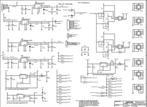
Back on the bench, a visual inspection shows the previously replace caps were fine. Testing the voltages at the connectors low voltages 5v, 3.3v, 24v etc all test fine. The only connector with no voltages is CN206 stencil with Vs, Gnd, and Va. This connector extends over to the left side board; I believe this to be the YSUS board.
I replace all 6 power MOSFET transistors SD20N60, just a wild shoot on the dark, still no voltage at the Vs and Va connector.
The PDP Service Manual I've found on a different board show Vs to be 188v-198v and Va to be 56v-61v. Without a P/S manual I’m at a lost trying to trace the path for either source.
The P/S part # stencil are YPSU-J013A and LGE PN:AAX30284301.
Any help with a P/S service manual or possible solutions is appreciated it.
Bu iyi bir soru mu?

6 Yorum
fastpacket2000, just wondering if this is the manual you have.
oldturkey03 tarafından
Oldturkey03,
Yes I have a copy of this Service Manual and also a copy of the LG PDP module Service manual. Unfortunately neither shows the power supply diagram.
The LG PDP manual was the only one that references the voltages at the Vs to be 188v-198v and Va 58v-61v. I back tracked the path from the connector as far as was able to go, to a row of power transformers (4) and up to the first set of power MOSFET’s with no high voltage at these areas.
The low voltage section is ok these are the 5v, 3.3v, 24v, etc and the set stays on but no picture or audio.
I’m now stuck in the mid-area trying to hand trace the circuitry on the P/S, and without a diagram is difficult to surmise what is what and where.
Thanks,
fastpacket2000 tarafından
Still trying to hunt down anything on the P/S. It may be easier to search for the Vizio version since apparently they use the same P/S I will post it asap...
oldturkey03 tarafından
Oldturkey03,
Thanks for you help..! Hope you have better luck in finding the manual.
PS: I found the Vizio VP50HDTV10A has a similar P/S from a picture and ModusLinkPTS cross reference the same P/S part # to other Vizio module but was not able to confirm them. Maybe this will help you in your search.
fastpacket2000 tarafından
Don't give up yet ;-), sometimes it takes me a little longer to get what I I am looking for....I will keep you in the know.
oldturkey03 tarafından
1 tane daha yorum göster