Giriş
Use this guide to replace the combined LCD / Touch Screen assembly as a single unit. It was inspired by the original ASUS VivoBook S400C Touch Screen Replacement guide.
Please note that the procedure for separating the display assembly from the top housing is incorrect in that guide and will result in damage to the touch screen bezel and/or the housing. Most of the videos on YouTube are similarly incorrect. If the tutorial does not start out by removing the display from the base, do not follow it.
The touch screen / LCD cannot be removed from the housing without breaking retainers unless the display assembly has been removed from the base of the computer.
As quoted from the original guide:
If your ASUS VivoBook S400C has a broken touchscreen or continues to have issues even after going through the touch screen trouble shooting guide to rule out any software issues, use this guide to replace it. Before you begin, make sure the laptop is completely turned off and the battery has been removed.
Warning: If the glass display is completely shattered, please remain safe by following the directions here on how to tape over any glass and prevent being hurt.
Note: Make sure the new screen has the same resolution and size as the original screen. You may get some help on finding this information by visiting this website.
Guides are also available for replacing the LCD or the touch screen individually.
Neye ihtiyacın var
-
-
Flip the device over and remove the ten 5.7 mm screws with a Phillips #0 screwdriver.
-
-
-
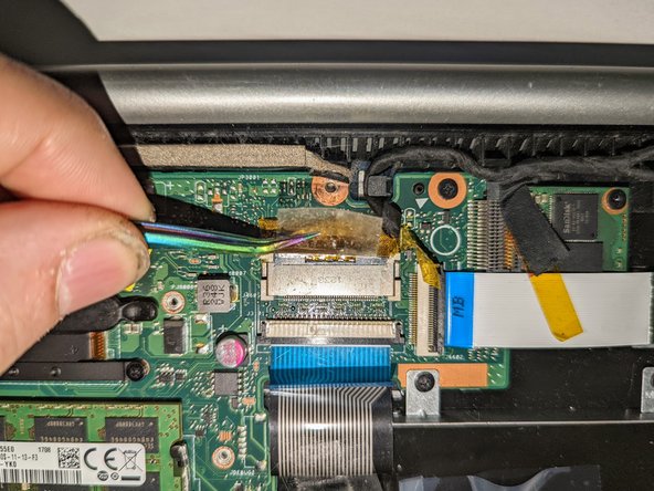
Using a spudger, lift up the plug connecting the battery to the motherboard.
-
-
-
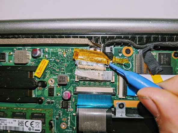
Remove the black shield covering the display connector and the heat sink.
-
-
-
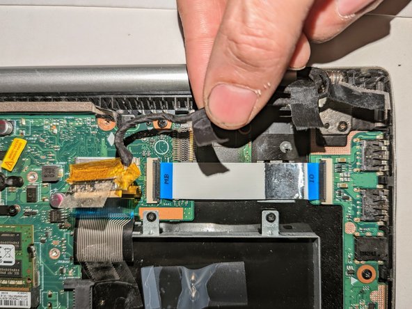
Remove the black tape securing the keyboard ribbon cable to the display connector.
-
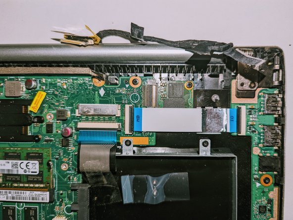
Fold the ribbon cable the opposite way, resecuring it to the hard drive to keep it out of the way.
-
-
-
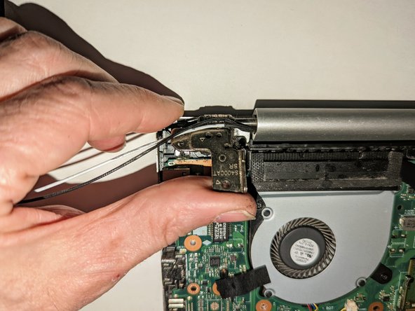
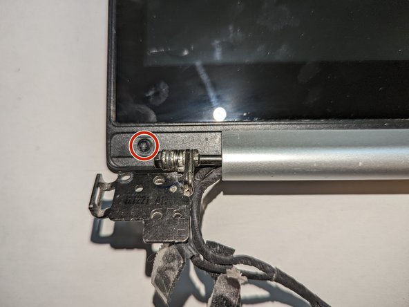
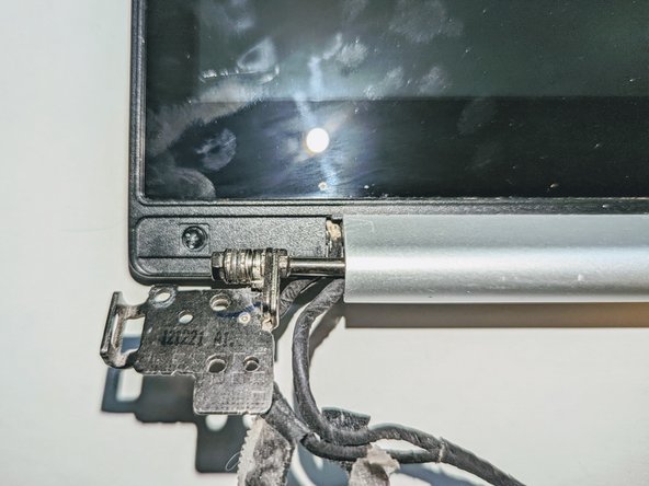
Remove the two screws securing the hinge on the left.
-
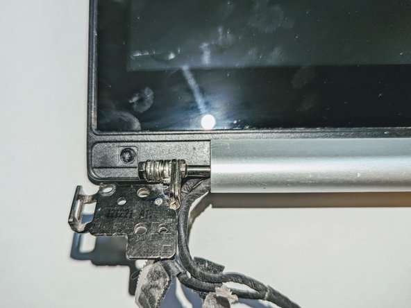
Pry the hinge up by hand to a 90 degree angle.
-
-
-
-
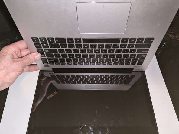
Lift the base of the laptop from the front.
-
Raise it to a 90 degree angle.
-
Slide it forward slightly to clear the hinges.
-
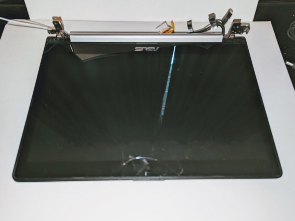
The display is now free.
-
-
-
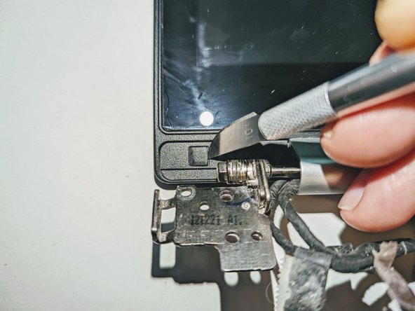
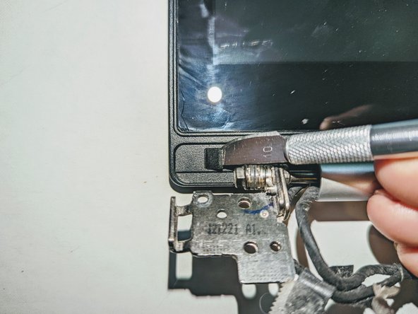
There are two black square plastic tabs covering the retaining screws. The tabs are fixed in place with light adhesive.
-
Using a thin blade, pry off the tabs covering the screws.
-
-
-
Grasp the hinge cover and slide it to the right. It will only move about 3mm (1/8 inch).
-
-
-
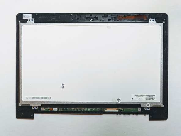
Slide the screen down to release the catches holding it in place.
-
-
-
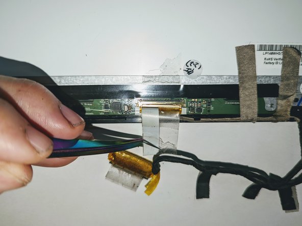
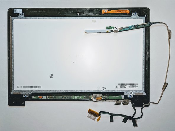
Flip the touch screen assembly over and peel the clear tape covering the LCD connector off the LCD panel.
-
-
-
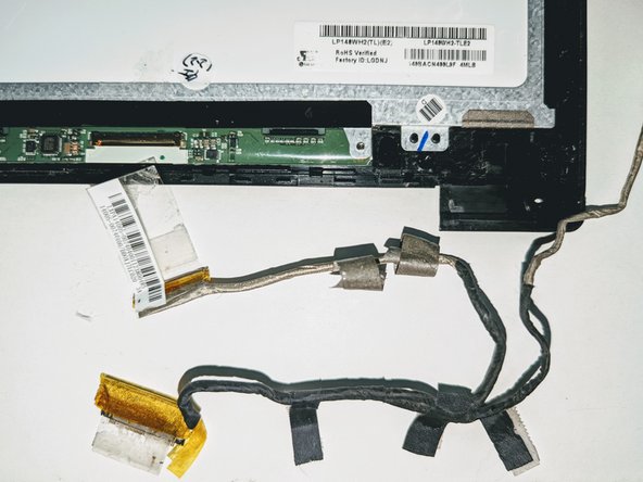
Peel off the tape providing a ground point to the LCD frame.
-
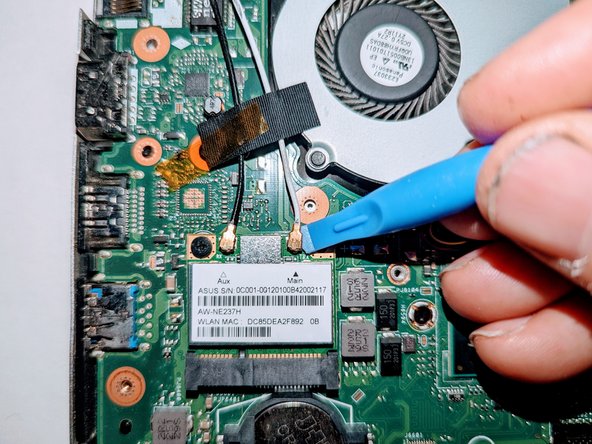
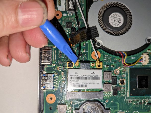
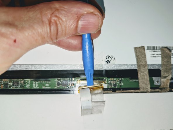
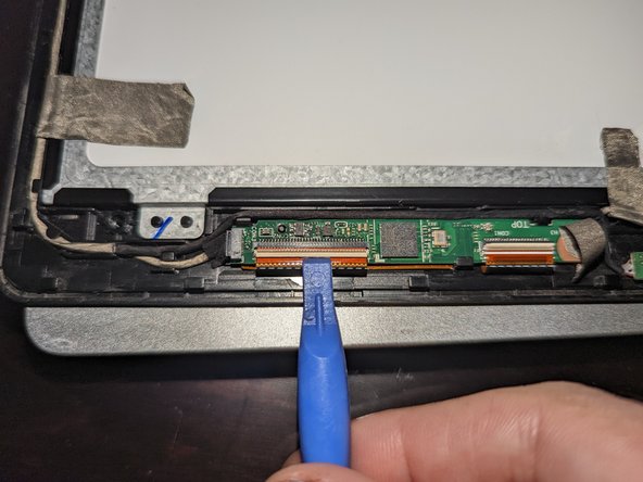
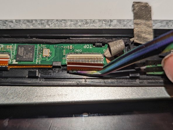
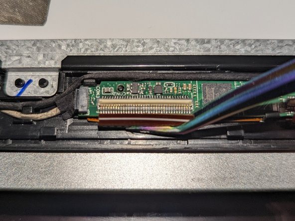
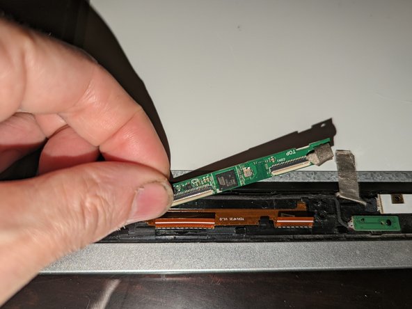
Use the flat end of a spudger to flip up the latch on the right connector.
-
-
-
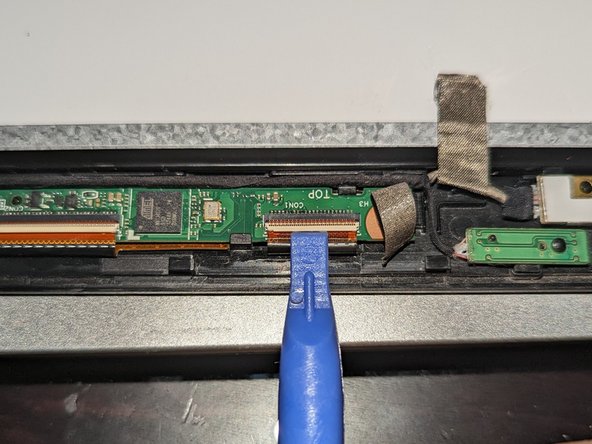
The touchscreen board is secured to the bezel with two latches on the far side and a plastic hook on the near side.
-
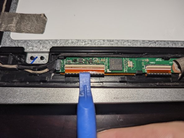
Use a spudger to open the right latch while gently prying up with an opening tool or a fingernail.
-
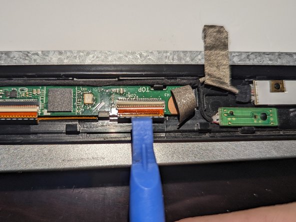
Use a spudger to open the left latch while gently prying up with an opening tool or a fingernail.
-
-
-
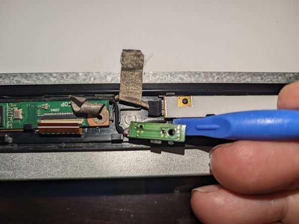
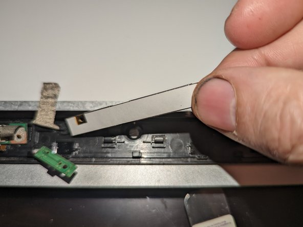
The microphone daughterboard is held in place by being pressed down onto a plastic pin.
-
Pry it up off the retaining pin with a plastic spudger.
-
-
-
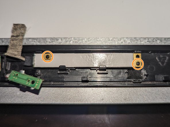
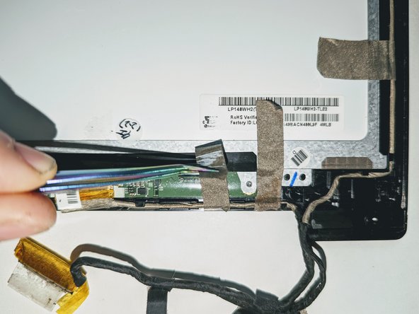
The camera daughterboard is held in place with two latches along the top of the board and two hooks on the bottom.
-
It is seated on two plastic guide pins as well.
-
-
-
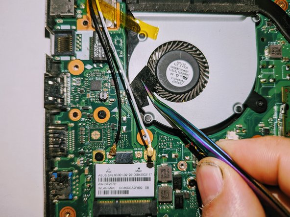
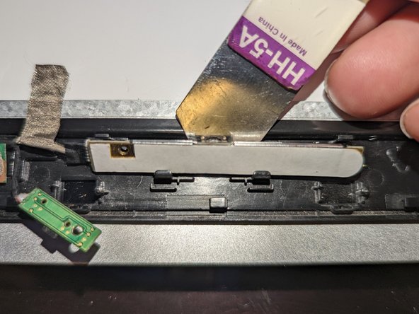
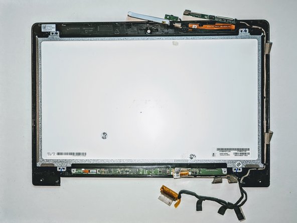
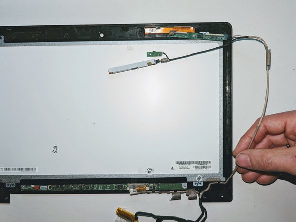
Carefully remove the five pieces of conductive tape securing the cables to the LCD frame.
-


To reassemble your device, follow these instructions in reverse order.
To reassemble your device, follow these instructions in reverse order.

Ekip
