Neye ihtiyacın var
-
-
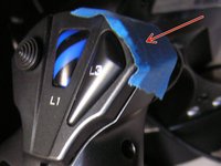
Remove the four 15 mm J1 JIS head screws from the exterior of the joystick.
-
-
-
Turn the controller upside down.
-
Remove the 20 mm J1 JIS head screw.
-
Remove the six 12 mm J1 JIS head screws.
-
Remove the two 6 mm J1 JIS head screws.
-
-
-
Gently pull the panel away from the controller.
My defective HOTAS 4 has a PCB marked HOTAS X PS4. Is this not selling short? From your picture I find that this PCB is different.
-
-
-
-
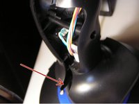
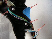
Place masking tape between the button panel and top of the right half of the handle, this will hold that assembly in place to protect the wires.
-
Separate the handle at the bottom and remove the center cover between the two halves. Set cover aside.
-
While holding the right half of the handle against the white center post, gently remove the left half of the handle with the trigger assembly and set aside.
-
-
-
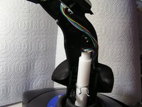
The right half of the handle should now be free to slide off of the square sensor body at the top of the white center post.
-
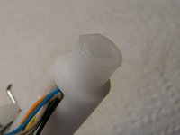
Lay down next to the white center post, being careful not to stress the wires.
-
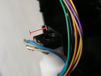
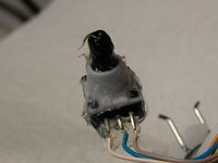
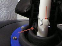
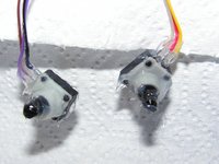
Lift the sensor body strait up and clear of the white center post. Note the orientation of the D-flat on the sensor "knob", it should be facing away from the solder tabs and towards the right half of the handle.
-
-
-
Use the Air Duster to blow out any debris inside the sensor, while turning the "knob" through it's entire range of motion several times. Hold the base and turn the knob so as not to bend the wires.
-
Use shop cloths to create a containment area and repeat the procedure using Silicone Spray, rotating the sensor several times with each wash. Wash at least three times to give any debris a chance to be flushed out.
-
Use Air Duster again to clear out any remaining silicon lube and to dry the part, again, rotating it through it's range of motion several times.
-
-
-
Encapsulate the sensor in Silicone Grease by working it into all the openings of the part on both ends.
-
Apply grease to the opening in the top of the white center post.
-
Apply grease to square receiving notch on the right handle.
-
-
-
Fit the right handle back onto the white central post. Wipe away excess grease.
-
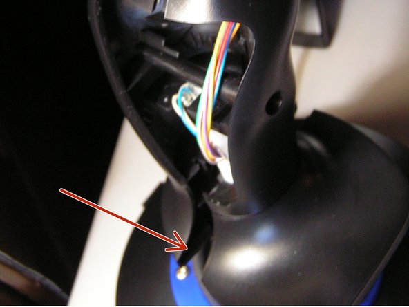
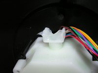
Tuck wires into the handle between screw bosses as shown. Ensure the three wires to the sensor are looped so that rotation of the handle does not tug on the wires.
-
Position in place the center cover, using masking tape to hold in place, if needed.
-
Slide the left handle in evenly from from the left until base mates up tight around the white center post and the top gives an audible click as it snaps into place.
-
Reinstall the screws in reverse order.
-
-
-
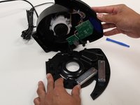
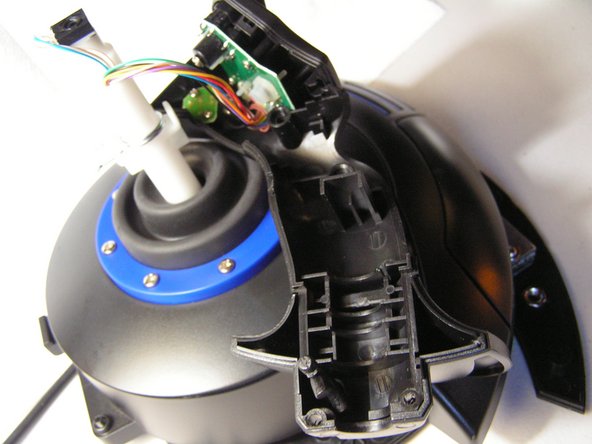
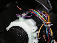
Remove the four 10mm J1 JIS head screws.
-
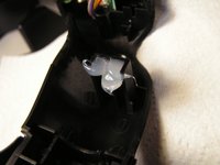
Pull the white assembly away from the cover and push the joystick handle toward the cover from the other side so that the sensors are accessible and free of the ribs in the cover that hold them in place.
-
Gently work each sensor out of it's mount, using care to support the fragile leads and wires. Note the orientation of the D-flat on each sensor "knob", the flat should be facing away from the solder tabs.
-
-
-
Refer to Step 7 for cleaning.
-
Encapsulate the sensor in Silicone Grease by working it into all the openings of the part on both ends.
-
Apply grease to the square receiving notch for each sensor and into the hole in the yoke assembly body.
-
-
-
Align the flats on the sensors to be opposite the solder tabs, as they were at removal, and gently seat each one into their square receiver notch. Wipe away excess grease.
-
Push the assembly back toward the cover while pulling the handle away from the cover on the other side, to seat the assembly onto the screw bosses.
-
Verify that the wire bundle coming in from the handle is not pinched between the assembly and the cover.
-
Reinstall the screws in reverse order.
-


Your t.Flight HOTAS is now ready to use. Be sure check that the firmware is up to date and that you have it configured to use the correct axis for your game software.
Your t.Flight HOTAS is now ready to use. Be sure check that the firmware is up to date and that you have it configured to use the correct axis for your game software.
İptal et: Bu kılavuzu tamamlamadım.
7 farklı kişi bu kılavuzu tamamladı.
7Kılavuz Yorumları
I am concerned about the sensitivity of this reconstruction. Have you had any experience with this build? Can I use it to play flappy bird quickly?
the repair does not change the sensitivity of the joystick at all... if anything it will make it more accurate with fewer false inputs.
skyfish -
Yes there is, I was in this place exactly. I did this with two, 2m lengths of CAT5 - painstakingly connecting, soldering and taping each of the 16 wires, one by one straight through. Straight through is essential or you'll get in a mess. Then tape up the join with 3M black and zip tie the CAT5 together. It works fine, if you do it carefully, and it looks the part too. I now have throttle and yoke either side of my Xrocker and it's perfect.
cgelse -
Great instructions. Managed to fix the stick drift on the stick rudder control pot by going up to step 9 and skipping steps 2-4. I used servitol Siwtch cleaner and coated with silicone grease, now works perfect!
the bottom 2 screws are slightly longer
skyfish - Yanıt