
DJI FPV Drone Disassembly

Giriş
1. adıma gitCrashes are part of life with a drone but fortunately, most parts are replaceable. However, disassembly is time consuming, requiring the removal of up to over 60 screws of many different types. This guide should enable you replace almost all the parts that might break.
A means of organising the screws is absolutely essential. My favourite method is to take a sheet of A4 paper and stick the screws from each step to it with a separate blob of blu-tac. Write the step number against each.
Most of the screws require a 1.5mm hex screwdriver bit but with a variety of lengths and shapes and sizes of heads. There are four requiring a 2.5mm hex bit. These are the main screws retaining the arms and are all accessed from within the battery compartment. Some of these may have their heads filled with gum making it impossible to engage a screwdriver. Worse, it my not be easily apparent as they are not easy to see. The gum can be removed with a dental pick or similar tool but you do need to get it all out. You will probably need a screwdriver extension as they are otherwise awkward to access, or you may be able to use a 2.5mm Allen key.
Additionally, there are a few Phillips 000 head screws and also a few with an even smaller cross head.
There are several miniature multi-way push-on connectors. These flip off easily with a spudger under a corner but care is required in reconnecting them. Exact alignment is essential but not always easy to see. Applying no more than firm finger pressure, you should feel it click into place. Confirm that it's engaged along its entire length by pressing each end in turn. You might feel another click. Never try to force it or you risk ireparable damage. If it doesn't click into place it invariably means it's misaligned.
The LEDs and sounders use very small connectors. It's important to disengage them by applying tweezers to the plug body, not by pulling the wires since they may pull out of the plug. Repair would probably be very difficult. A pair of tweezers, a good light and possibly a magnifying glass or eye loupe are almost essential in order to reengage them, unless you can enlist the services of a tame fairy.
Solder connections are used from the motor control board to the motors for higher reliability than detachable connectors would be likely to give at the high currents that the motors take. You will need a soldering iron if removing or repacing any of the arms.
-
-
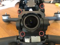
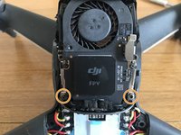
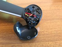
Remove 4 screws retaining the camera cover.
-
Ease off the camera cover.
-
-
-
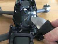
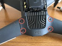
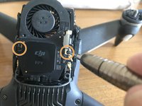
Remove 2 screws on each side retaining the canopy.
-
Ease off the canopy with a jimmy or plastic spudger.
-
-
-
Remove 4 screws securing the gimbal.
-
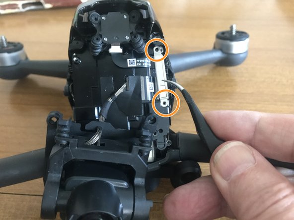
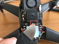
Remove 2 screws securing a retaining clip and lift it off.
-
Lift off the two press-in connectors under the clip, then gently peel the black sticky tape, allowing the gimbal and its cable to be removed.
-
-
-
On either side of the metal piece covering the IMU there are 2 Phillips 000 screws, one screwing inwards and one screwing downwards. Remove these and lift off this metal piece.
-
-
-
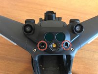
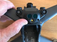
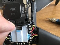
Facing the back of the drone, remove two screws retaining te optical sensor unit.
-
The optical sensor is also retained by two clips underneath it. With both thumbs, push it up firmly from the bottom to release it. (In the photo, my other thumb was holding the camera.)
-
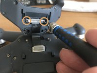
Turn the optical sensor over, in an upwards direction, and remove two screws to release the retaining clip.
-
With a spudger or similar tool, gently lidt a corner of the connector to disconnect it.
-
-
-
-
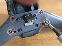
Remove 4 screws in the cover beneath where the optical sensor was.
-
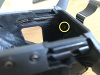
Remove two screws at the inboard underside ends of the front arms.
-
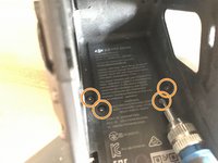
Locate two screws retaining the front arms, accessible from deep within the bttery comparment. These have 2.5mm hex heads. Loosen them by a few turns only. You will most likely need a screwdriver extension, or a 2.5mm allen key. Don't remove them.
-
You should now be able to pull each of the front arms out by a millimetre or so enabling you to remove the cover.
-
Feed the ribbon cable back through the slot in the cover as you remove it.
-
-
-
Remove two screws on each side of the top rear cover and remove the cover starting to pry from the bottom
-
Remove 4 screws in the floor of the battery compartment.
-
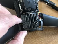
Remove the heat sink. In fact it may just fall off as it will only be held by the stickiness of the heat-conducting mastic.
-
-
-
Loosen 2 screws at the top ends of 2 retaining clips for the antenna connectors.
-
Remove the two screws at the bottom ends of these clips and remove the clips.
-
You can now remove the bug filter.
-
If you will need to remove the arms, lift off the U.FL antenna connectors on the side that you need to work on.
-
-
-
Lift off the the GPS U.FL antenna connectors.
-
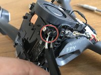
Remove a screw on either side of the GPS unit. These have very fine Phillips heads, smaller than 000. One of the heads may be covered with a black coating which should be scraped off
-
Remove the retainer clip which the screw on the right secured. The top of the clip is held by the board.
-
Lift off the connector which the clip retained. You can now remove the GPS unit.
-
-
-
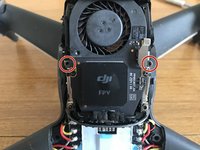
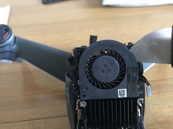
Disconnect the fan connector.
-
The fan is retained by double-sided tape and can now be prised off with a jimmy under the top edge.
-
-
-
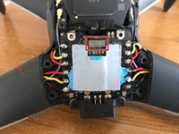
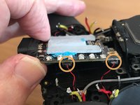
Each of the 4 motors has 3 wires soldered to the motor control board. The colours should be the same as in the photo. Were you to accidentally reverse any two on reconnecting them, the corresponding motor would spin backwards, causing an instant crash on take-off.
-
Unsolder all 12 wires (or only the 6 on one side if you are simply replacing an arm).
-
Lift off the connector at the top of the motor control board.
-
-
-
Remove 2 screws securing a rear arm on each side (or only on the side of an arm you are replacing).
-
Remove the screw accessed from within the battery compartment retaining each rear arm. These have 2.5mm hex heads and were previously loosened.
-
You should now be able to gently ease off the rear arms.
-
-
-
Remove the screw (2.5mm head), accessible from within the battery compartment retaining each front arm.
-
Feed the sheathed cable to each front arm back through its conduit in the battery compartment.
-
You should now be able to gently ease off each front arm.
-
-
-
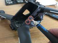
Both the front and rear arms have covers on the bottom secured by two screws. Remove these screws.
-
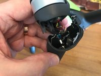
In the case of the front arm there is a small board next to the motor with 3 connectors. One receives LED power from the motor control board, a second connects to a LED within the arm itself, and the third is a U.FL antenna connector. Disconnct all three if you need to transfer the board to a replacement arm.
-
The front arms are similar except that a somewhat larger board extends into the leg.
-
-
-
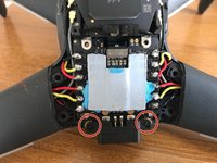
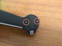
Disconnect a very small connector on each side. (These are for the sounder).
-
Remove a long screw on each side.
-
Remove a short screw on each side. (Ensure that it is indeed the short screw that you use here on reassembly.)
-
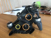
The two circuit boards at right angles should now lift off.
-
There is also a sounder on each side which must be prised off and refitted to the new central frame. Again, take care to correctly route the cable.
-
-
-
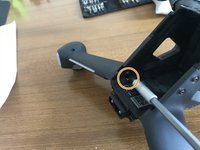
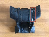
In the case of an arm break, it may actually be the arm stub on the central frame which is broken. In the photo it was a fairly clean break and has been glued with epoxy glue but it may not be as strog as the original. Better to fit a replacement.
-
Carefully prise off the foam piece on each side containing a GPS antenna and apply it to the new central frame. Make sure the antenna lead is correctly routed.
-
There is also a sounder on each side which must be prised off and refitted to the new central frame. Again, take care to correctly route the cable.
-


To reassemble your device, follow these instructions in reverse order.
To reassemble your device, follow these instructions in reverse order.
İptal et: Bu kılavuzu tamamlamadım.
3 farklı kişi bu kılavuzu tamamladı.

Ekip
