
Dell Alienware 14 Display Hinges Replacement

Giriş
1. adıma gitIn this guide, we will show you how to remove and replace the Display Hinges.
Neye ihtiyacın var

-
-
Align the tabs on the NEW base cover with the slots on the computer base and slide the base cover into place.
-
-
-
Replace the screws that secure the base cover to the computer base.
-
-
-
Disconnect the battery cable from the system-board connector.
-
-
-
Using the battery cable, lift the battery and release it from the tabs on the computer base.
-
-
-
Turn the computer over and open the display as far as possible.
-
-
-
Press and hold the power button for five seconds to ground the system board.
-
-
-
Align the tabs on the NEW battery with the slots on the computer base.
-
-
-
Align the screw holes on the battery with the screw holes on the computer base.
-
-
-
Remove the screws that secure the secondary hard-drive assembly to the computer base.
-
-
-
Carefully lift the secondary hard-drive assembly and then lift the latches to release the secondary hard-drive cable from the system-board connector.
-
-
-
Lift the secondary hard-drive assembly off the computer base.
-
-
-
Remove the screw that secures the secondary hard-drive assembly to the main bracket.
-
-
-
Remove the screws that secure the secondary hard-drive to the secondary hard-drive bracket.
-
-
-
Slide and lift the secondary hard-drive off the secondary hard-drive bracket.
-
-
-
Disconnect the interposer from the secondary hard-drive connector.
-
-
-
Connect the interposer to the secondary hard-drive connector.
-
-
-
Place the NEW secondary hard-drive in the secondary hard-drive bracket.
-
-
-
Align the screw holes on the secondary hard-drive with the screw holes on the secondary hard-drive bracket.
-
-
-
Replace the screws that secure the secondary hard-drive to the secondary hard-drive bracket.
-
-
-
Align the screw hole on the secondary hard-drive assembly with the screw hole on the main bracket.
-
-
-
Replace the screw that secures the secondary hard-drive assembly to the main bracket.
-
-
-
Slide the secondary hard-drive cable into the system-board connector and press down on the connector latches to secure the cable.
-
-
-
Align the screw holes on the secondary hard-drive assembly with the screw holes on the computer base.
-
-
-
Replace the screws that secure the secondary hard-drive assembly to the computer base.
-
-
-
Lift the connector latch and pull the pull-tab to disconnect the status-light board cable from the system-board connector and slide the cable into the slot on the computer base.
-
-
-
Remove the screws that secure the palm -rest assembly to the computer base.
-
-
-
Turn the computer over and open the display as far as possible.
-
-
-
Using a plastic scribe, pry the palm-rest assembly from the computer base.
-
-
-
Release the connector latches to disconnect the flexi-cable from the system board.
-
-
-
Follow the instructions from step 1 to step 9 in Removing the Keyboard.
-
Follow the instructions from step 1 to step 4 in Removing the Status-Light Board.
-
Follow the instructions from step 1 to step 4 in Removing the Speakers.
-
Follow the instructions from step 1 to step 4 in Removing the Power-Button Board.
-
-
-
Follow the instructions from step 1 to step 4 in Replacing the Power-Button Board.
-
Follow the instructions from step 1 to step 3 in Replacing the Speakers.
-
Follow the instructions from step 1 to step 4 in Removing the Status-Light Board.
-
Follow the instructions from step 1 to step 8 in Replacing the Keyboard.
-
-
-
Connect the flexi-cable to the connector on the system board.
-
-
-
Turn the NEW palm-rest assembly over and slide the status-light board cable through the slot on the computer base.
-
-
-
Align the palm-rest assembly over the computer base and snap the palm-rest assembly into place.
-
-
-
Replace the screws that secure the palm-rest assembly to the computer base.
-
-
-
Slide the status-light board cable into the system-board connector and press on the connector latch to secure the cable.
-
-
-
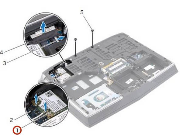
Disconnect the display and camera cables from the system-board connectors.
-
-
-
Disconnect the antenna cables from the wireless mini-card.
-
-
-
Remove the screws that secure the display assembly to the computer base.
-
-
-
Turn the computer over and open the display as far as possible.
-
-
-
Remove the display, camera, and antenna cables from the slots on the computer base.
-
-
-
Note the display, camera and antenna cable-routing and remove the cables from their routing guides.
-
-
-
Remove the screws that secure the display assembly to the computer base.
-
-
-
Align the screw holes on the NEW display assembly with the screw holes on the computer base.
-
-
-
Replace the screws that secure the display assembly to the computer base.
-
-
-
Route the display, camera, and antenna cables through the routing guides.
-
-
-
Replace the screws that secure the display assembly to the computer base.
-
-
-
Connect the display and camera cables to the system-board connectors.
-
-
-
Using your fingertips, carefully pry up the inside edge of the display bezel
-
-
-
Align the NEW display bezel with the display back-cover, and gently snap the display bezel into place.
-
-
-
Remove the screws that secure the display hinges to the display back-cover.
-
-
-
Align the screw holes on the NEW display hinges with the screw holes on the display back-cover.
-
-
-
Replace the screws that secure the display hinges to the display back-cover.
-


To reassemble your device, follow these instructions in reverse order.
To reassemble your device, follow these instructions in reverse order.

Ekip
