Giriş
This repair guide was authored by the iFixit staff and hasn’t been endorsed by Google. Learn more about our repair guides here.
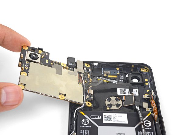
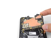
This guide shows how to replace the front facing selfie camera for the Pixel 3a. Since the camera is connected to the motherboard’s underside, you will have to remove the motherboard in order to remove the camera.
The Pixel 3a’s unreinforced display panel is fragile. If you are reusing the screen, be sure to pay special attention to the warnings in the opening procedure.
The trickiest part of the procedure is re-attaching the proximity sensor connector, which requires some patience and finesse.
Neye ihtiyacın var
-
-
Insert a SIM eject tool, SIM eject bit, or a paper clip into the SIM tray hole.
-
Press to eject the tray.
-
-
-
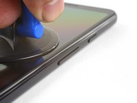
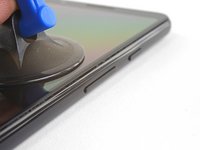
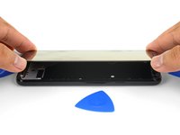
Take note of the two seams on the phone:
-
Screen seam: This seam separates the screen from the rest of the phone. This is where you should pry.
-
Frame seam: This is where the plastic frame meets the back cover. It is held in place by screws. Do not pry at this seam.
-
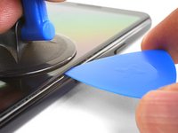
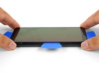
Before you begin prying, note the following areas on the screen:
-
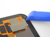
Screen flex cable: Do not pry deeper than instructed, or you risk damaging this cable.
-
Adhesive perimeter: Prying beyond the narrow perimeter without angling the pick will damage the display panel.
-
-
-
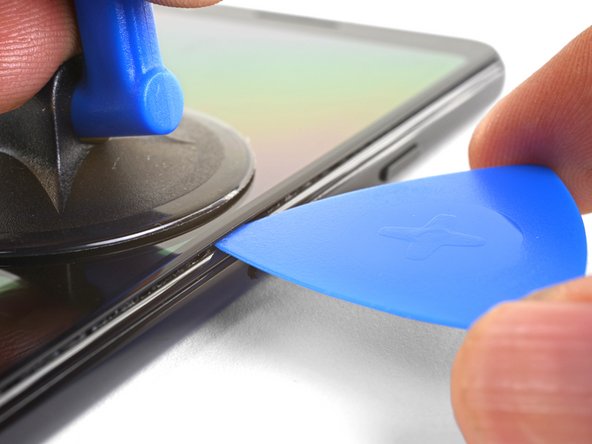
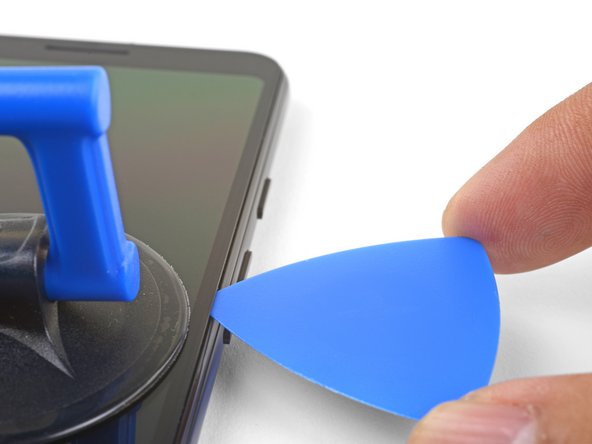
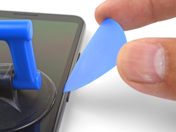
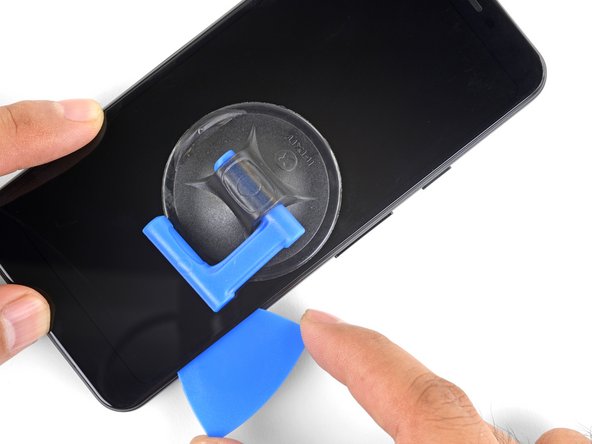
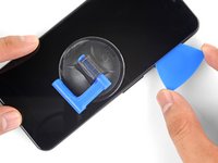
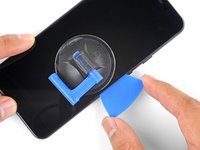
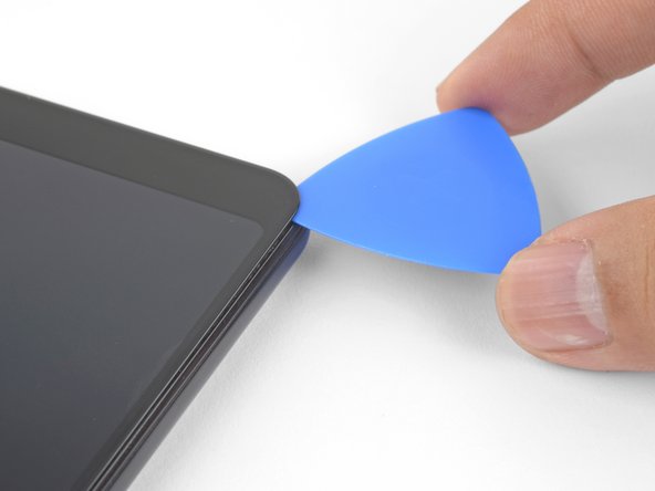
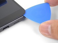
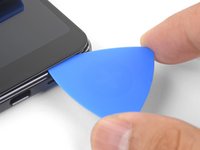
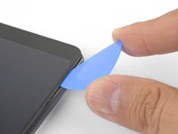
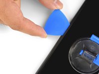
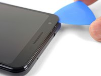
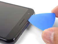
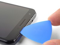
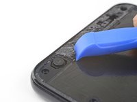
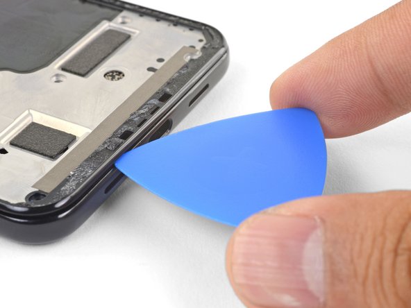
Slice through the left edge of the phone, making sure to properly angle the pick below the OLED panel and insert it in no more than 1/4" (6 mm).
-
To angle the pick below the OLED panel, insert the point of the pick no more than 1 mm in, angle the pick upwards, and then slowly push the pick in 1/4".
-
-
-
-
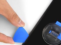
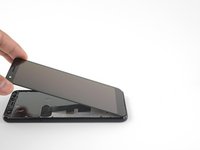
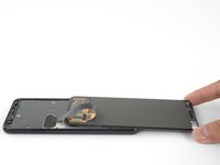
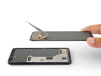
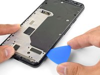
Remove the screen.
-
Carefully compare your replacement screen with your original part. You may need to transfer additional components (such as the speaker mesh) to the new part.
-
Follow this guide if you are using custom-cut adhesives.
-
If you are using double-sided tape such as Tesa tape, follow this guide.
-
-
Bu adımda kullanılan alet:Magnetic Project Mat$19.95
-
Remove the fourteen T3 screws of the following lengths securing the plastic midframe:
-
Twelve 4.3 mm silver T3 screws
-
Two 4.3 mm black T3 screws
-
-
-
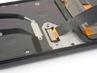
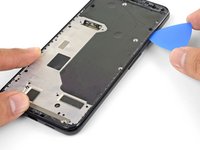
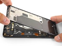
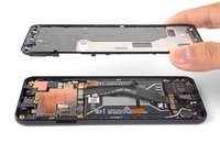
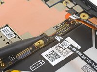
Align the top edge of the plastic midframe with the phone.
-
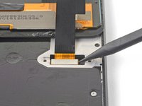
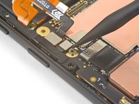
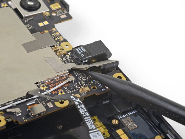
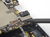
Use the point of a spudger to carefully align and push the proximity sensor connector onto the motherboard socket.
-
This takes a bit of patience and finesse. Once you have the connector in place, you can also use a finger to gently press the connector onto the socket.
-
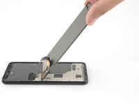
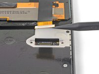
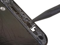
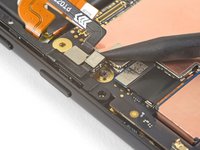
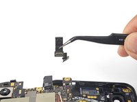
Use the point of a spudger to carefully pry the proximity sensor out of its recess on the midframe. The sensor is lightly adhered to the midframe.
-
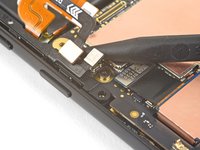
Remove the sensor from the midframe. Attach the sensor connector onto its motherboard socket.
-
Thread the sensor cable through the midframe and reposition the sensor in the recess. Press down with your finger to adhere the sensor back onto the midframe.
-
-
-
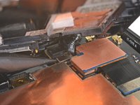
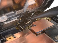
Use the point of a spudger to pry up and disconnect the battery connector from its motherboard socket.
-
Bend the battery flex cable slightly so that it will not accidentally make contact with the socket.
-
-
-
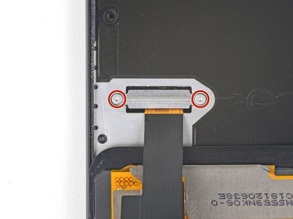
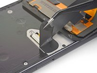
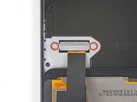
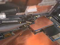
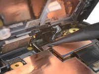
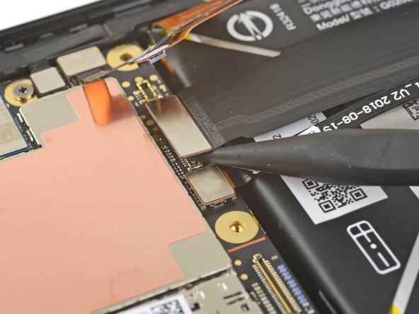
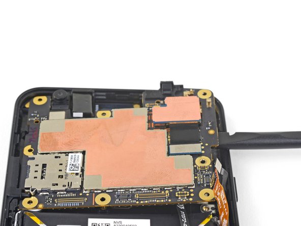
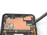
Use the point of a spudger to pry up and disconnect the interconnect flex cable from its motherboard socket.
-


To reassemble your device, follow these instructions in reverse order.
Repair didn’t go as planned? Check out our Google Pixel 3a Answers community for troubleshooting help.
To reassemble your device, follow these instructions in reverse order.
Repair didn’t go as planned? Check out our Google Pixel 3a Answers community for troubleshooting help.
İptal et: Bu kılavuzu tamamlamadım.
2 farklı kişi bu kılavuzu tamamladı.


1Rehber Yorum
This was super helpful! My phone was in for repair last year at a Google ASP for a front camera failure, but then it happened again a few months later, along with intermittent “phone is getting warm” warnings, and the display adhesive letting go. Upon removal of the midframe screws, I discovered that only two or three of them were fully driven, with the rest being significantly loose. I don’t believe the midframe was making good contact with the thermal blocks on the logic board. Further, when I removed the logic board, I discovered that the front camera flex was completely unplugged from the logic board. Perhaps the loose midframe allowed the camera to move around and work its connector loose. I seated the connector and confirmed it was solid, the front camera is now working, and I’ve fully reassembled the device. It seems less laggy as well! I guess I have a spare front camera now.