Giriş
This repair guide was authored by the iFixit staff and hasn’t been endorsed by Google. Learn more about our repair guides here.
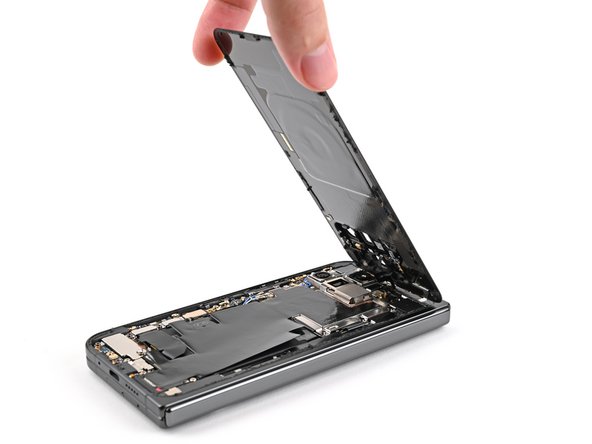
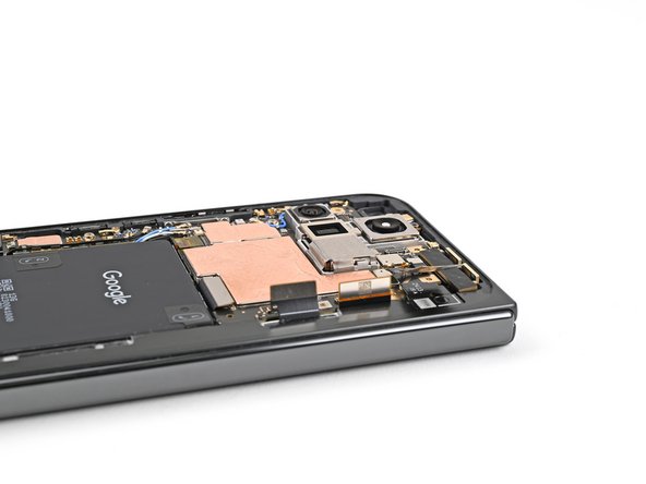
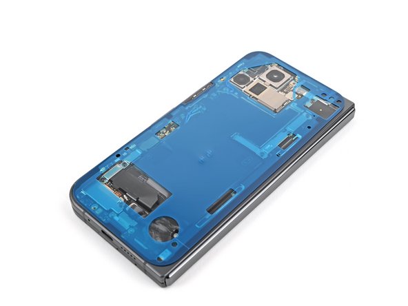
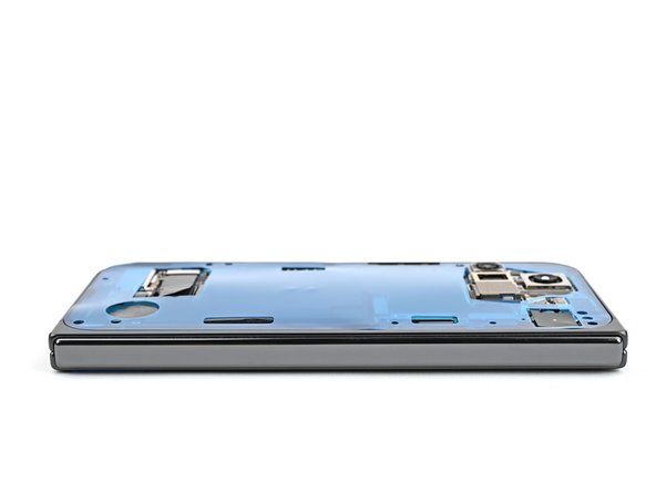
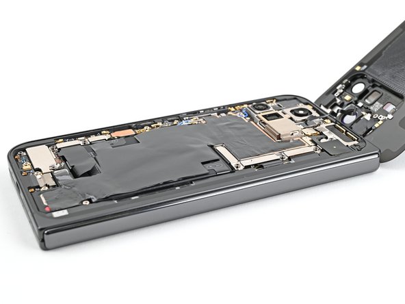
Use this guide to replace the USB-C port board in your Google Pixel 9 Pro Fold.
Neye ihtiyacın var
-
-
Unplug all cables from your phone and completely power it down.
-
-
-
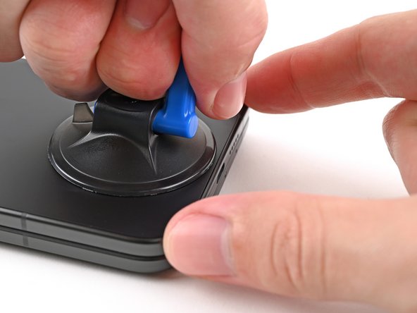
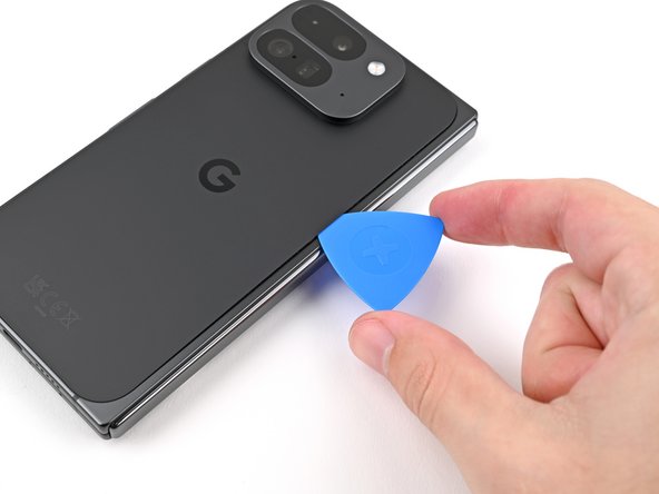
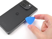
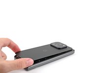
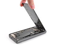
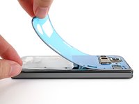
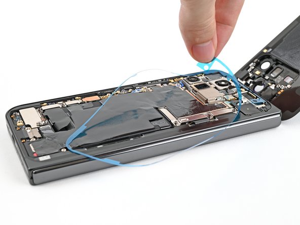
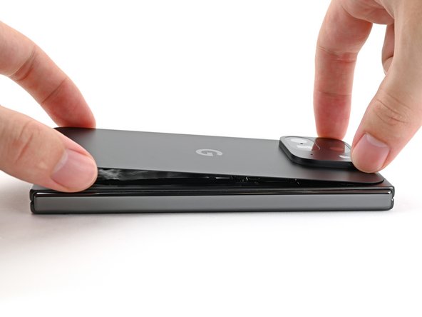
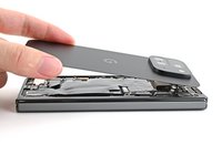
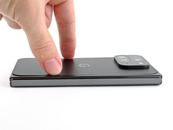
Apply a suction cup to the back cover, as close to the center of the bottom edge as possible.
-
While securing the phone with one hand, pull up on the suction cup with strong, steady force to create a gap between the back cover and the frame.
-
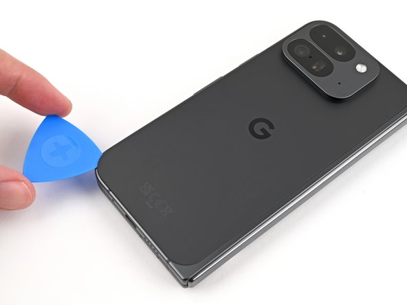
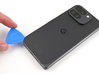
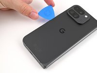
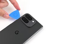
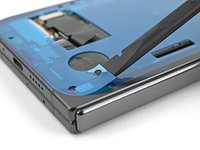
Insert an opening pick into the gap.
-
-
-
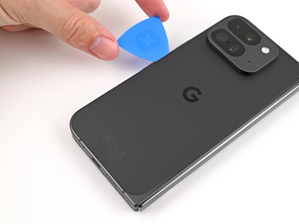
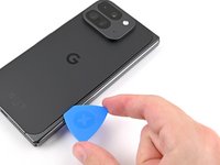
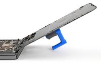
Remove the suction handle from the back cover.
-
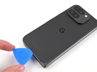
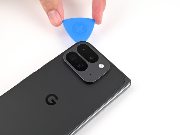
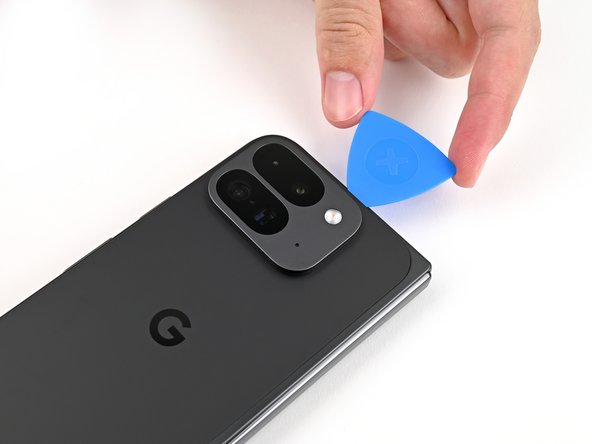
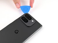
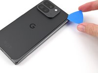
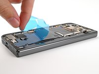
Slide the opening pick around the bottom left corner and up the left edge of the back cover to separate the adhesive.
-
-
Bu adımda kullanılan alet:FixMat$36.95
-
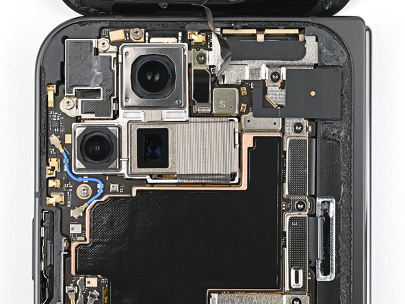
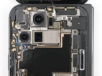
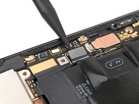
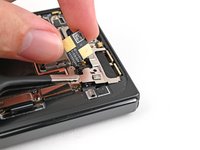
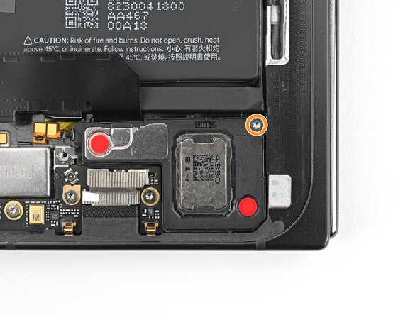
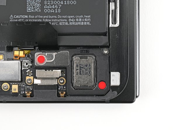
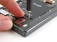
Use a Torx Plus 3IP driver to remove the 3.0 mm‑long screw securing the top bracket.
-
-
-
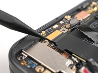
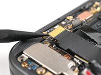
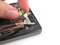
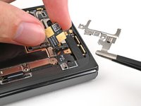
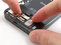
Use tweezers, or your fingers, to pull the top bracket towards the top of the phone to release it from its clip.
-
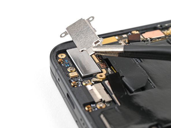
Remove the top bracket.
-
-
-
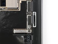
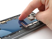
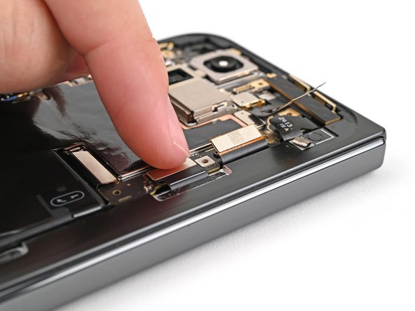
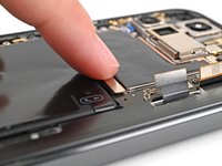
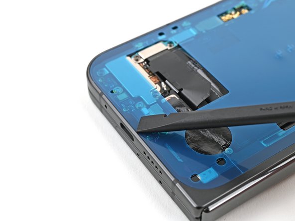
Insert the tip of your spudger under the bottom edge of the back cover cable press connector.
-
Pry up and disconnect the back cover cable.
-
-
-
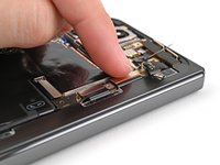
Use a Torx Plus 3IP driver to remove the two 3.0 mm‑long screws securing the base battery bracket.
-
-
-
Use tweezers, or your fingers, to pull the base battery bracket toward the bottom of the phone to release it from its clip.
-
Remove the base battery bracket.
-
-
-
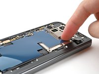
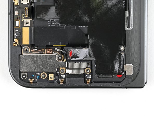
Insert the tip of your spudger under the bottom left corner of the base battery press connector, near the gold marker.
-
Pry up and disconnect the base battery.
-
-
-
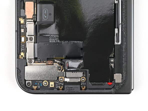
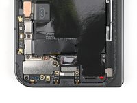
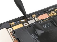
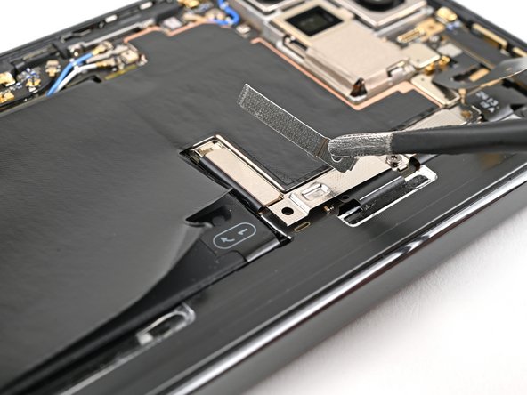
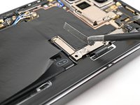
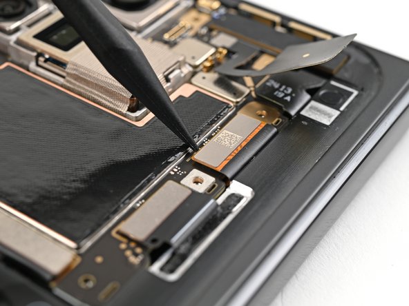
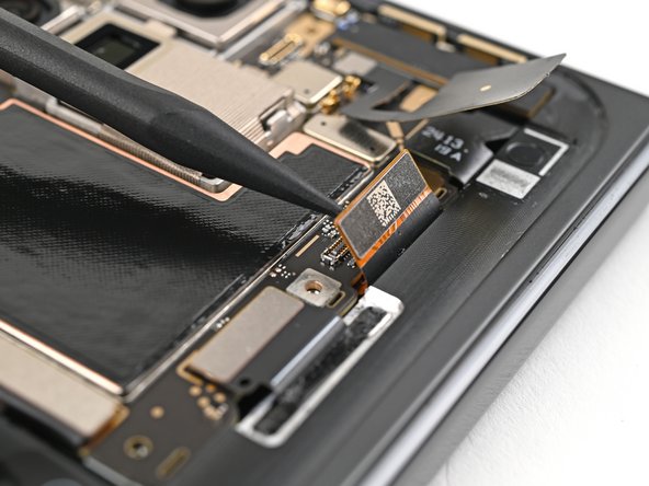
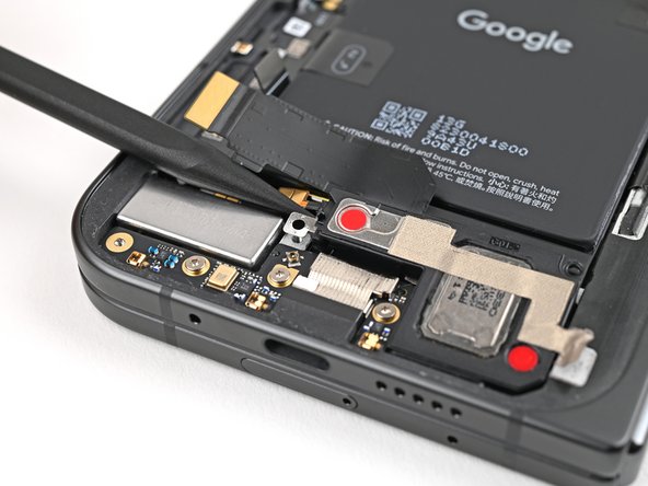
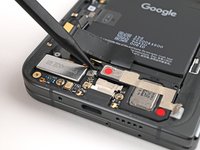
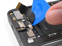
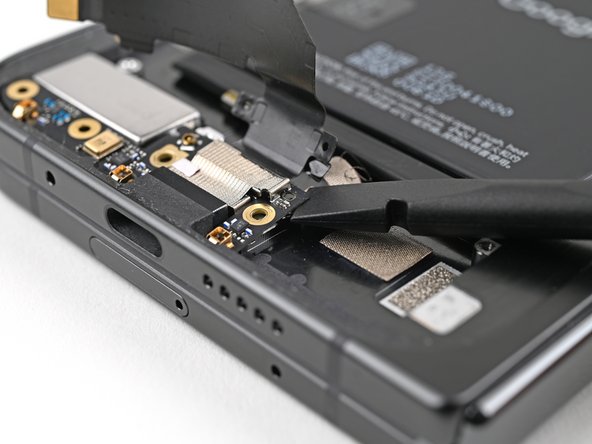
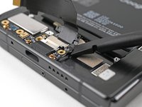
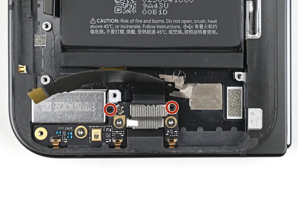
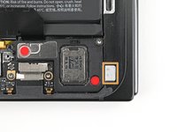
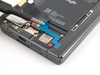
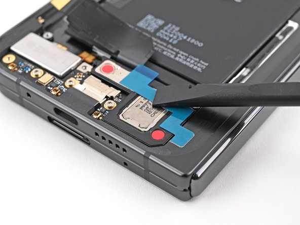
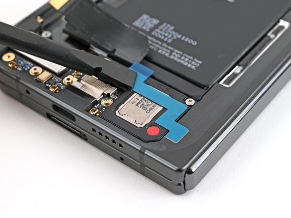
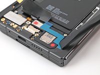
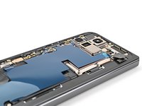
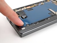
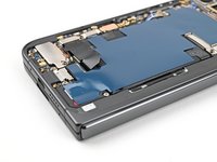
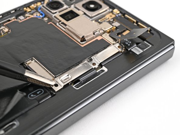
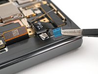
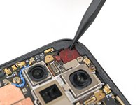
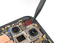
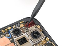
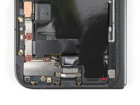
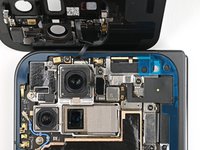
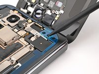
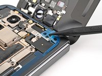
Use a spudger to pry up and disconnect the USB-C port board cable press connector.
-
-
-
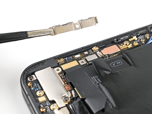
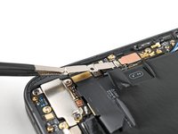
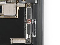
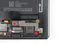
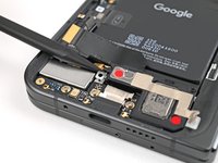
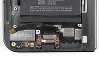
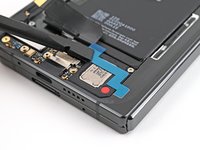
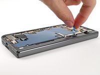
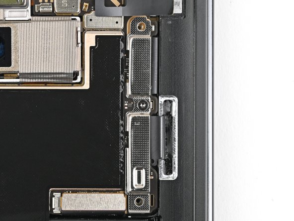
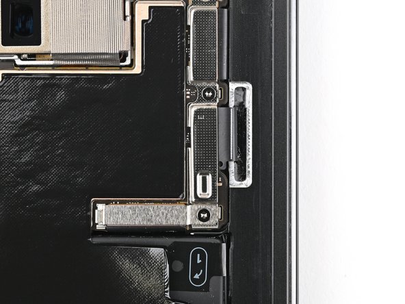
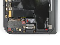
Use a Torx Plus 3IP driver to remove the two 3.0 mm‑long screws securing the vibrator bracket.
-
-
-
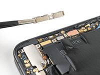
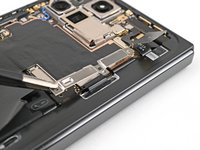
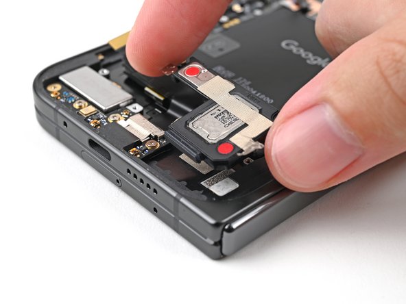
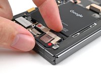
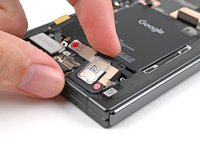
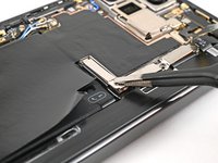
Use tweezers, or your fingers, to lift the vibrator bracket off the frame and remove it.
-
-
-
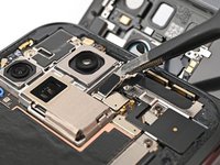
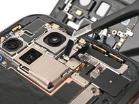
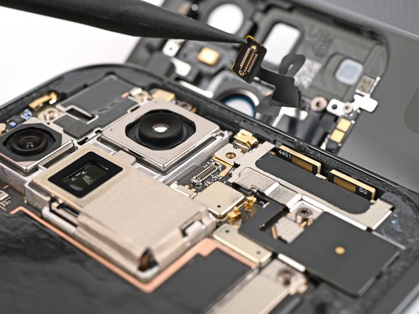
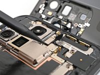
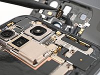
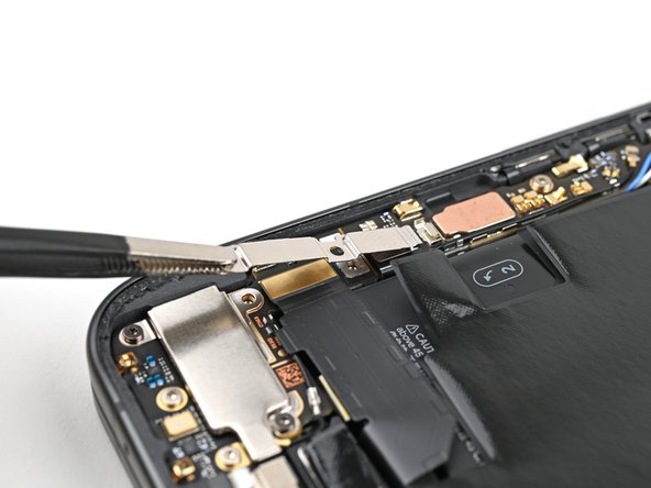
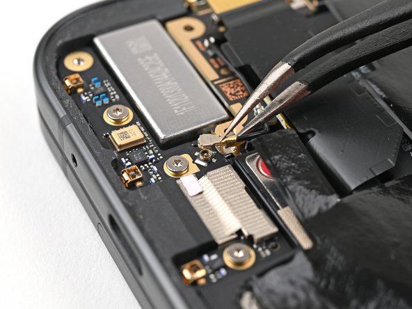
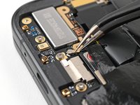
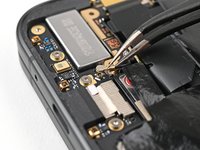
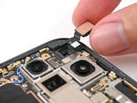
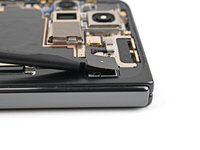
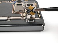
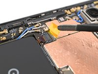
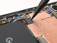
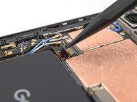
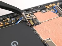
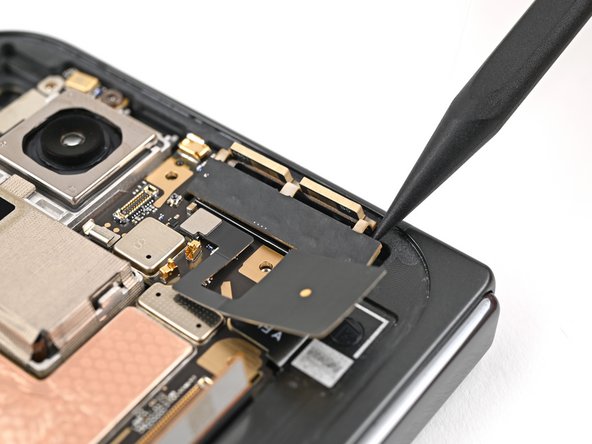
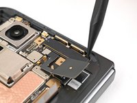
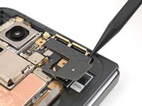
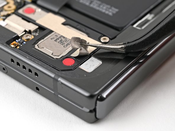
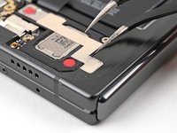
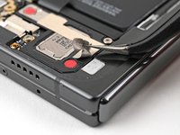
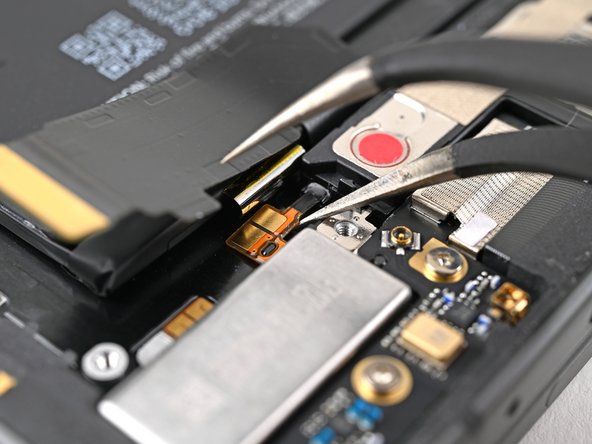
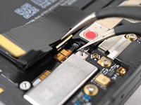
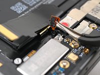
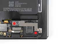
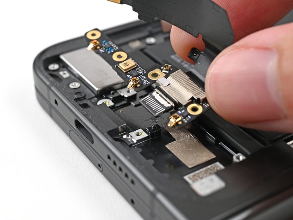
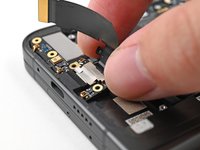
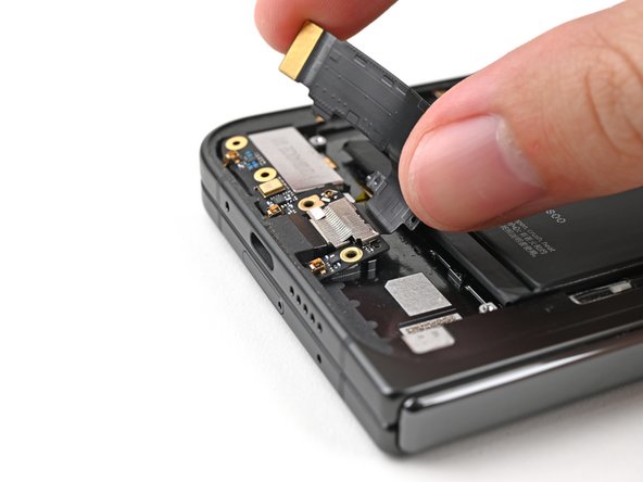
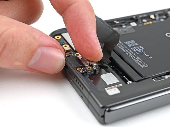
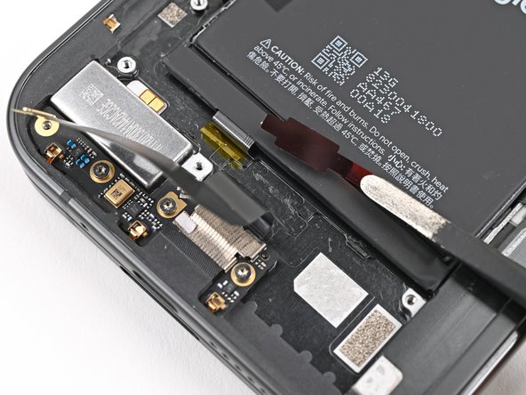
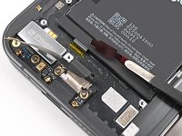
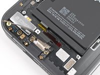
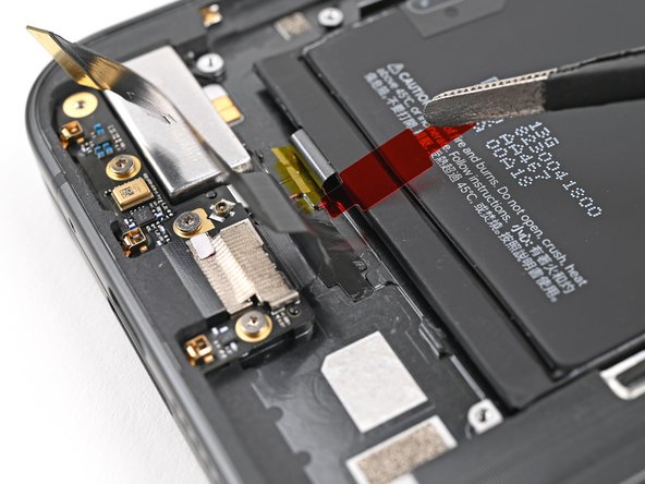
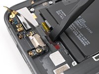
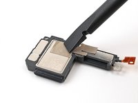
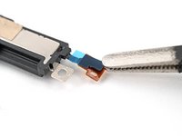
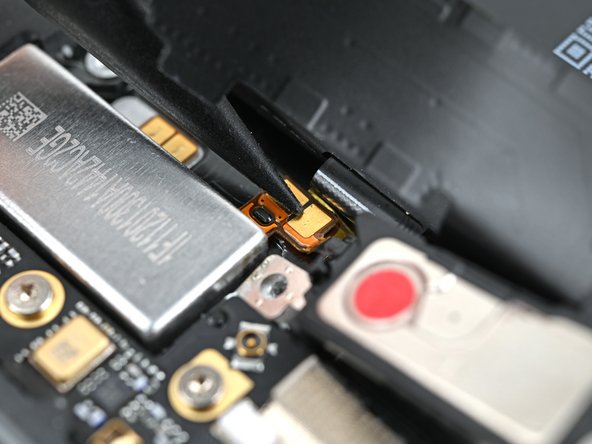
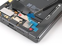
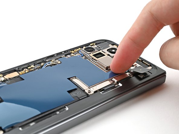
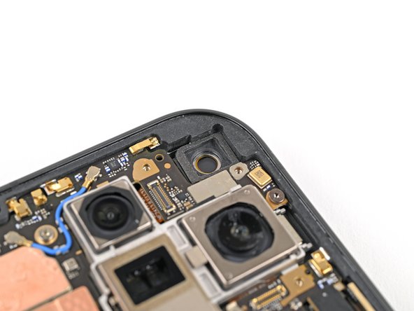
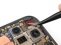
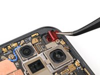
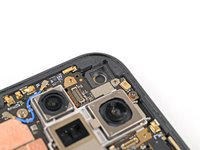
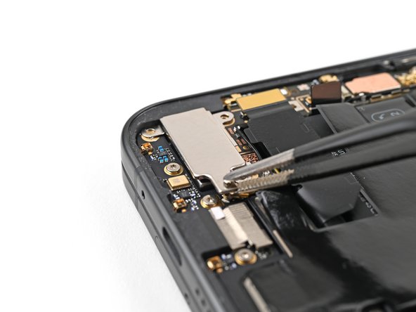
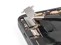
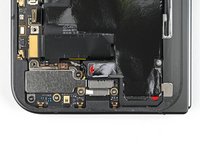
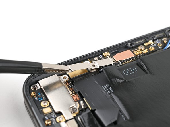
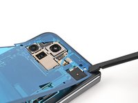
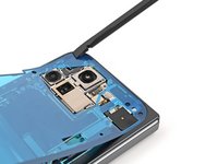
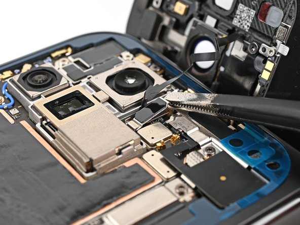
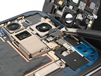
Slide one arm of a pair of angled tweezers under the metal neck of the black antenna cable's connector head on the USB‑C board.
-
Lift straight up to disconnect the cable.
-
-
-
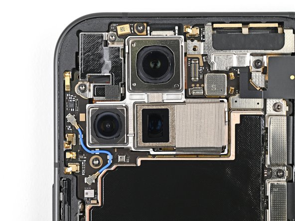
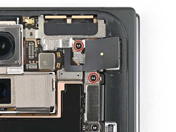
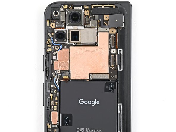
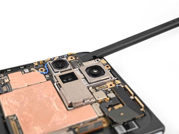
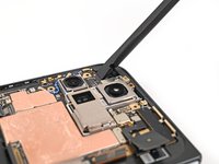
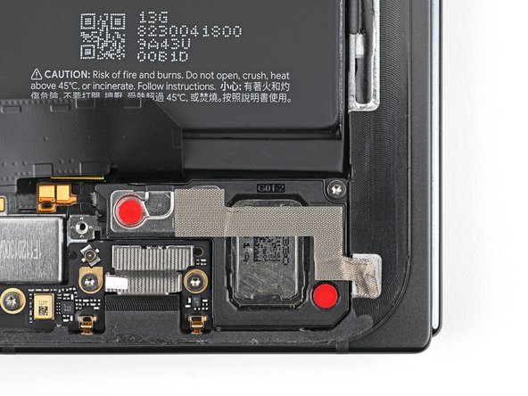
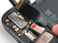
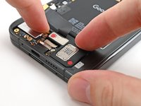
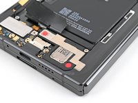
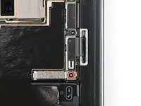
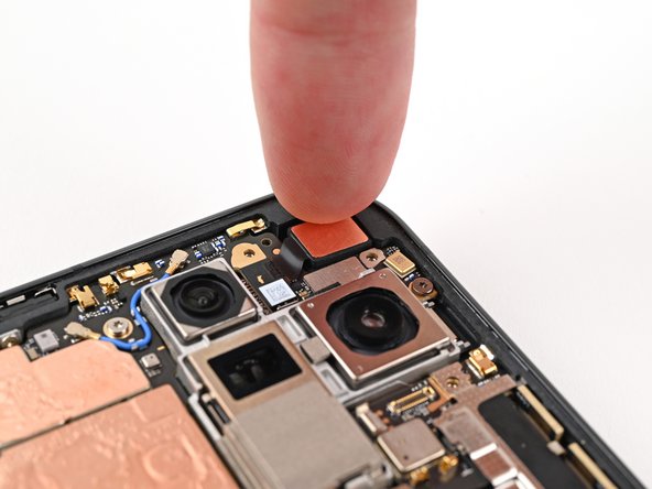
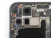
Use a Torx Plus 3IP driver to remove the two 2.6 mm‑long screws securing the inner front camera bracket.
-
-
-
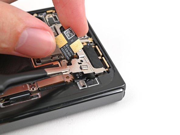
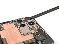
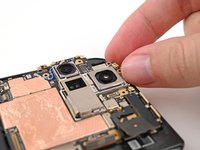
Use tweezers, or your fingers, to lift the inner front camera bracket up and toward the left edge of the phone to release its clips.
-
Remove the inner front camera bracket.
-
-
-
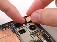
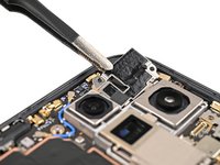
Use a spudger to pry up and disconnect the inner front camera press connector.
-
-
-
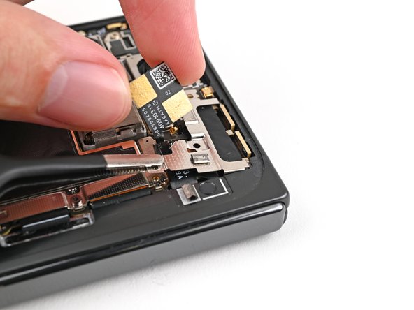
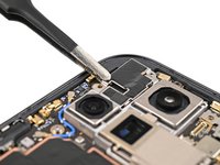
Use the point of a spudger to pry up the inner front camera and separate the adhesive securing it to the frame.
-
Remove the inner front camera.
-
-
-
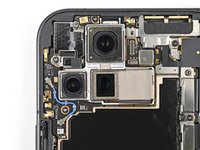
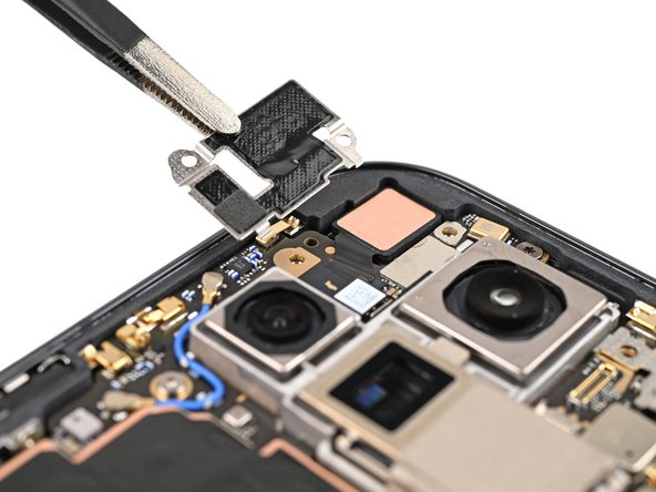
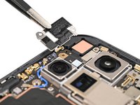
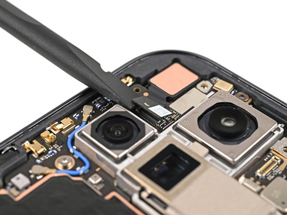
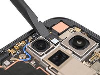
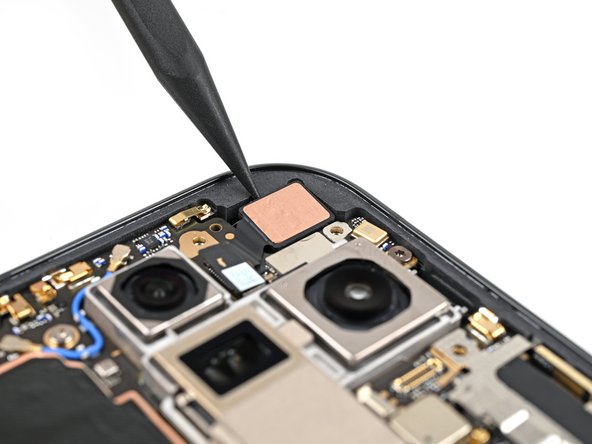
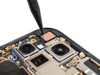
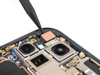
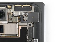
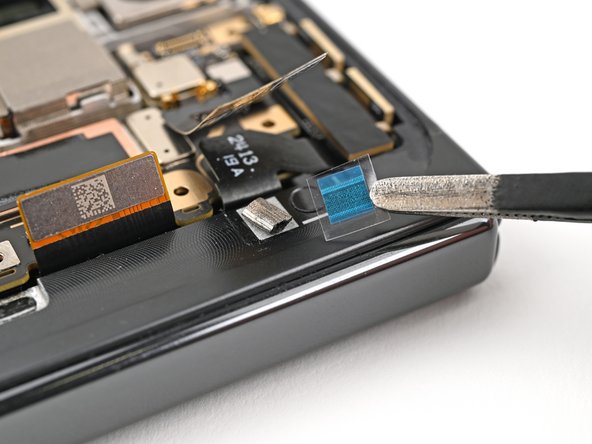
Slide the flat end of a spudger under the ultra wideband antenna to separate the adhesive foam securing it to the frame.
-
Use tweezers, or your fingers, to lift the antenna off the frame to separate any remaining adhesive.
-
-
-
Use a Torx Plus 3IP driver to remove the two 3.0 mm‑long screws securing the ultra wideband bracket.
-
-
-
While holding the ultra wideband antenna out of the way, pull the bracket toward the bottom of the phone to release its clips.
-
Remove the ultra wideband bracket.
-
-
-
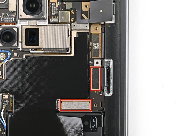
Use a Torx Plus 3IP driver to remove the 3.0 mm‑long screw securing the interconnect cable bracket.
-
-
-
Use tweezers, or your fingers, to pull the bracket toward the right edge of the phone to release its clip.
-
Remove the bottom interconnect cable bracket.
-
-
-
Use a Torx Plus 3IP driver to remove the 3.0 mm‑long screw securing the inner display cable bracket.
-
-
-
Use tweezers, or your fingers, to pull the inner display cable bracket towards the left edge of the phone to release it from its clip.
-
Remove the inner display cable bracket.
-
-
-
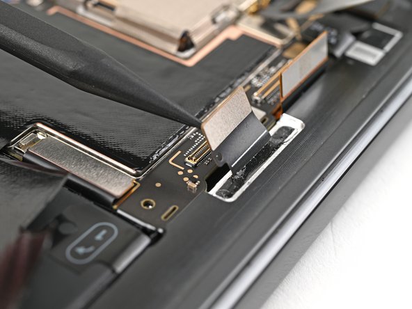
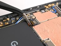
Insert the point of a spudger under the bottom left corner of the inner display press connector, next to the gold marker on the logic board.
-
Pry up and disconnect the inner display cable.
-
-
-
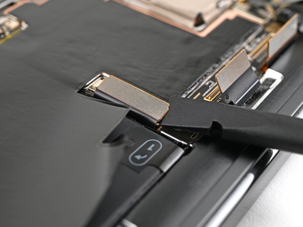
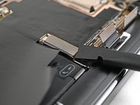
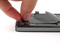
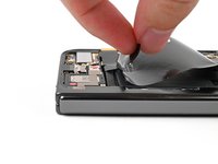
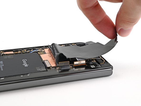
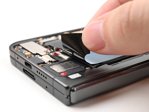
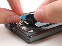
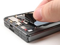
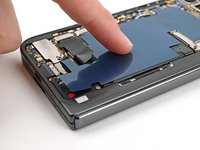
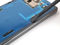
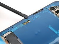
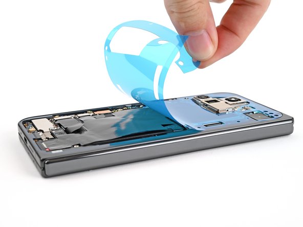
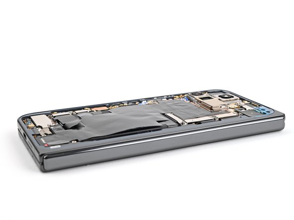
Peel the graphite sheet off the bottom speaker to separate the adhesive securing it.
-
-
-
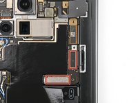
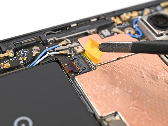
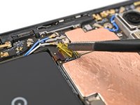
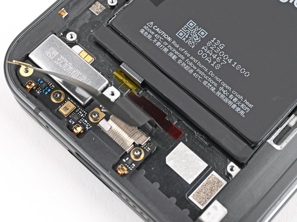
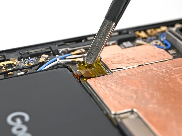
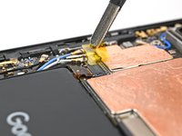
Use tweezers, or your fingers, to peel off the yellow tape on the side button cable ZIF connector.
-
-
-
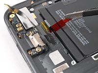
Use the tip of a spudger to pry up the 5G mmWave antenna from the frame and separate it from the thermal pad.
-
-
-
Use a Torx Plus 3IP driver to remove the three screws securing the logic board:
-
One 2.2 mm‑long screw
-
Two 2.6 mm‑long screws
-
-
-
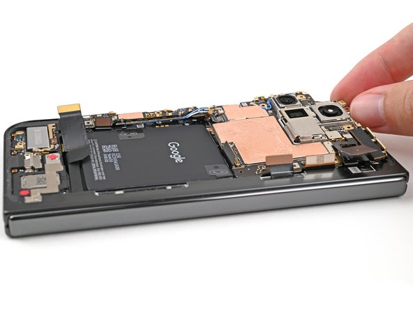
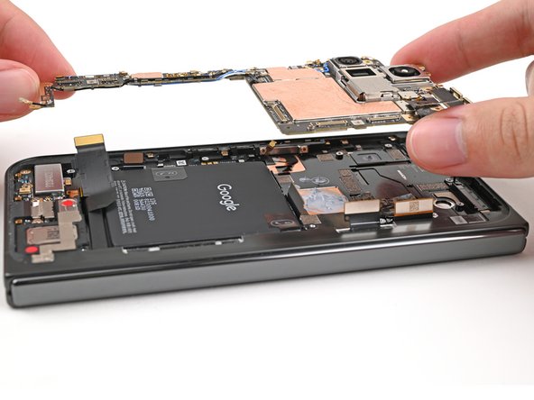
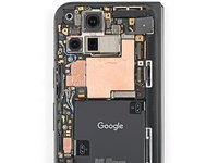
Insert the flat end of a spudger under the top left corner of the logic board, next to the inner front camera cutout.
-
Pry up the logic board enough so you can grip the top edge with your fingers.
-
-
-
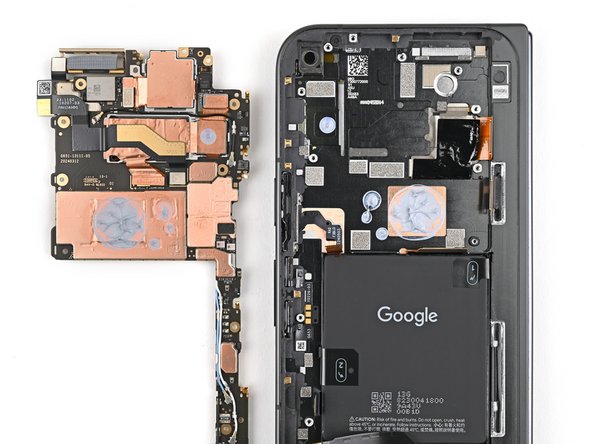
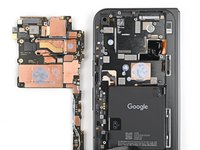
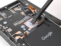
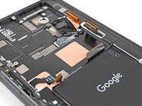
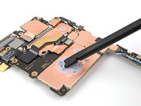
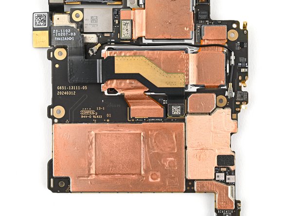
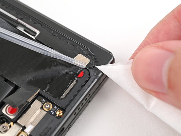
Use the flat end of a spudger to scrape away large pieces of old thermal paste from the frame.
-
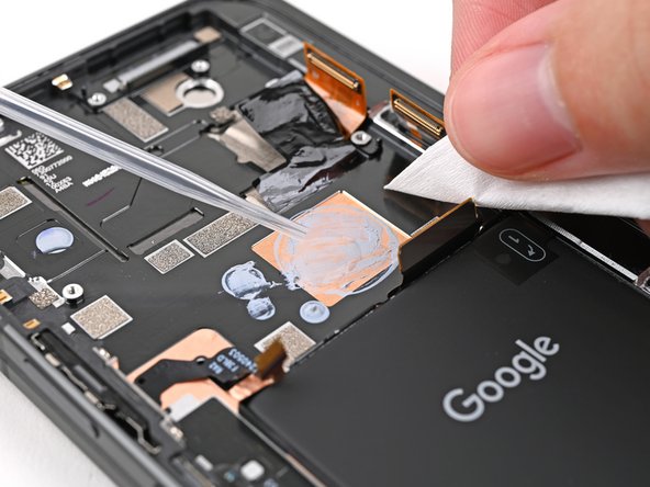
Apply a few drops of highly-concentrated isopropyl alcohol (over 90%) to any remaining thermal paste residue.
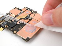
-
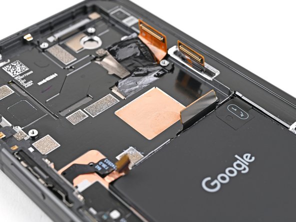
Wipe away the residue using a coffee filter or lint-free cloth.
-
-
-
-
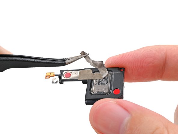
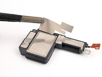
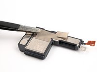
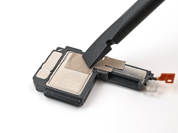
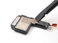
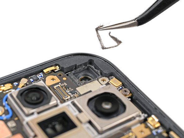
Use tweezers, or your fingers, to peel the section of conductive fabric connecting the loudspeaker to the frame.
-
-
-
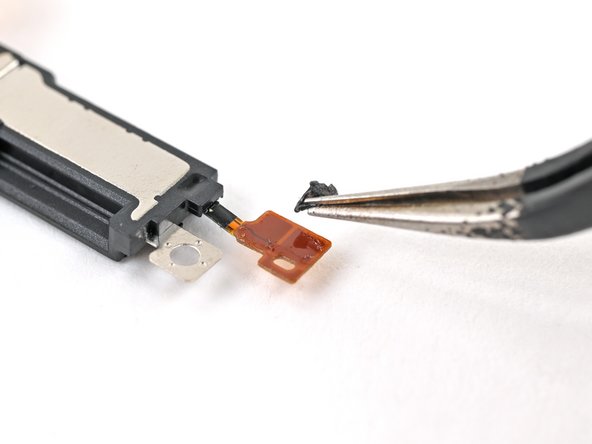
Slide one arm of a pair of angled tweezers under the contact pad connected to the loudspeaker.
-
Lift the contact pad to separate the adhesive securing it to the frame.
-
-
-
Use a Torx Plus 3IP driver to remove the 2.6 mm‑long screw securing the loudspeaker.
-
-
-
Use the tip of a spudger to pry up the left edge of the loudspeaker to separate the adhesive securing it to the frame.
-
-
-
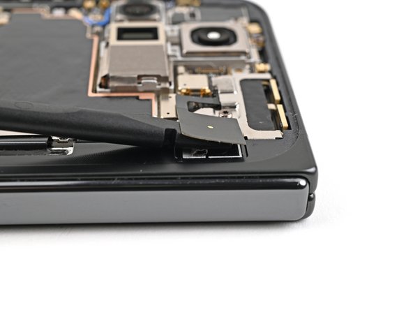
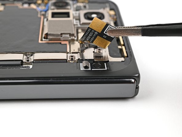
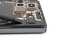
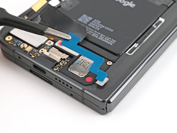
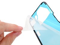
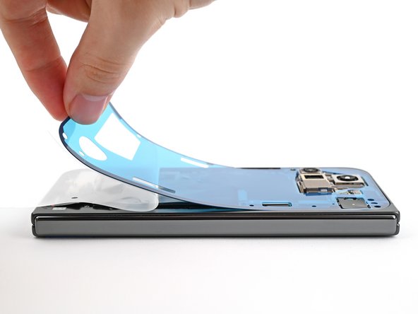
Slide the tip of an opening pick under the USB-C port board cable to separate the adhesive securing it to the frame.
-
-
-
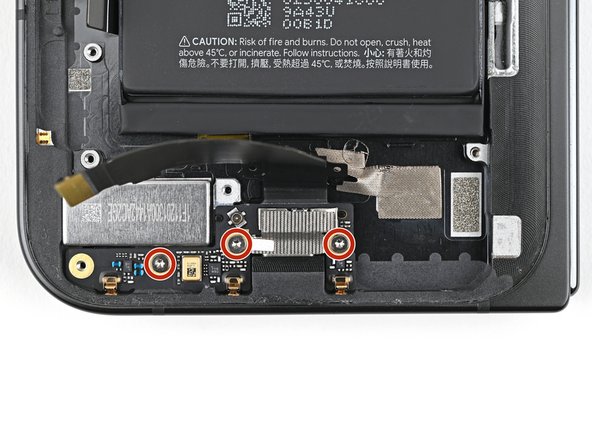
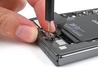
Use a Torx Plus 3IP driver to remove the three 2.6 mm‑long screws securing the USB-C port board.
-
-
-
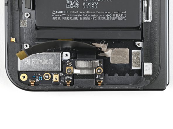
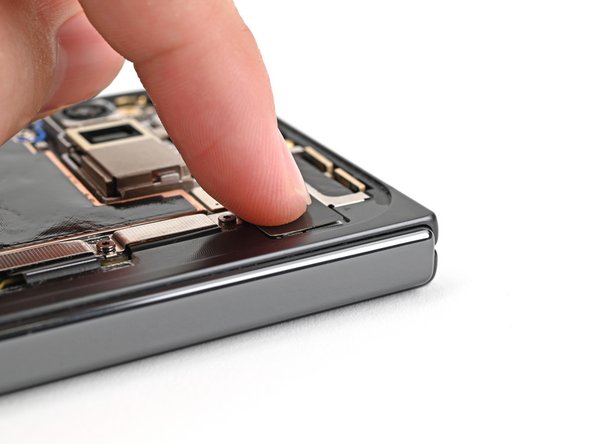
Use a spudger to pry up the top right corner of the USB-C port board to unclip it from the frame.
-
-
-
Congratulations on completing disassembly! The remaining steps will show you how to reassemble your device.
-
-
-
Reinsert the USB-C port board into its recess in the frame.
-
-
-
Press the USB-C port board flat to the frame to re-engage the metal springs, making sure the alignment pegs fit into their holes in the board.
-
-
-
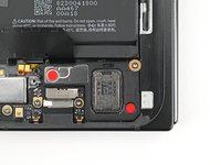
Use tweezers, or your fingers, to remove the old adhesive under the USB-C port cable.
-
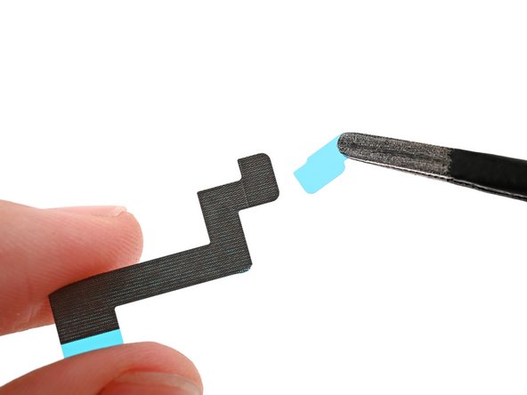
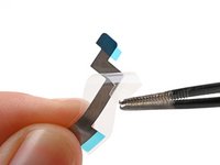
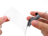
Peel the new USB-C port cable adhesive strip from its clear liner.
-
Align the adhesive strip over its spot in the frame and lay it down with the colored pull tab facing the right edge of the phone.
-
-
-
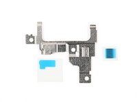
Use tweezers, or your fingers, to remove the bottom and top conductive fabrics or the loudspeaker cable adhesive if they're not intact.
-
-
-
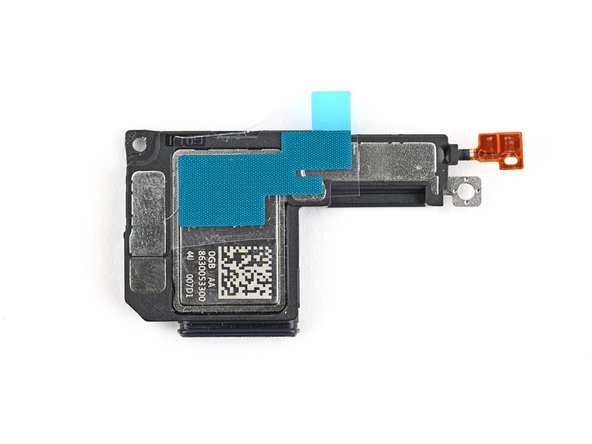
Align the bottom loudspeaker conductive fabric on the underside of the loudspeaker.
-
-
-
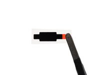
Peel the clear liner off the loudspeaker cable adhesive.
-
Align the adhesive over the loudspeaker cable and lay it down, making sure not to cover the hole in the cable.
-
-
-
Align the hole in the loudspeaker cable over its peg on the frame.
-
Press down the cable with the tip of a spudger, or your finger, to adhere it to the frame.
-
-
-
Peel off the clear liner on the top loudspeaker conductive fabric.
-
Peel off the small colored liner covering the rounded corner of the fabric.
-
-
-
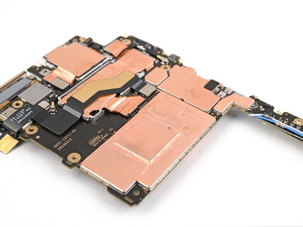
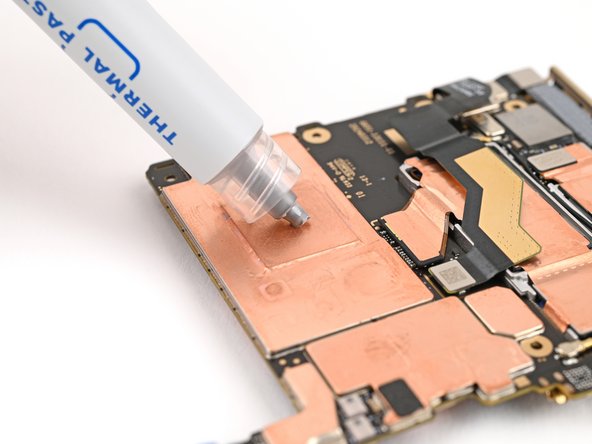
Apply small beads of thermal paste (five total) to the motherboard in the same locations as the old thermal paste.
-
-
-
Place the logic board back into its cutout in the frame, making sure no cables get trapped underneath it.
-
-
-
Use angled tweezers to push the side button cable back into its slot.
-
-
-
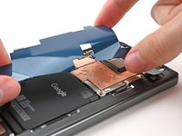
Peel the clear liner off your replacement graphite sheet to expose the adhesive on the upper half.
-
Align the upper half of the graphite sheet over the logic board and lay it down.
-
-
-
Reconnect the inner display cable and the top and bottom interconnect cable press connectors.
-
-
-
Reinsert the inner display cable bracket clip under its slot in the logic board and align the screw holes.
-
-
-
Reinsert the bottom interconnect bracket clip under its slot in the frame and align the screw hole.
-
-
-
While holding the ultra wideband antenna out of the way, reinsert the ultra wideband bracket clip under its slot in the frame and align the screw holes.
-
-
-
Remove the old adhesive and foam on the ultra wideband bracket and under the antenna.
-
Replace the corresponding adhesive and foam to the bracket and the frame.
-
Press the ultra wideband antenna to the frame and re‑adhere it.
-
-
-
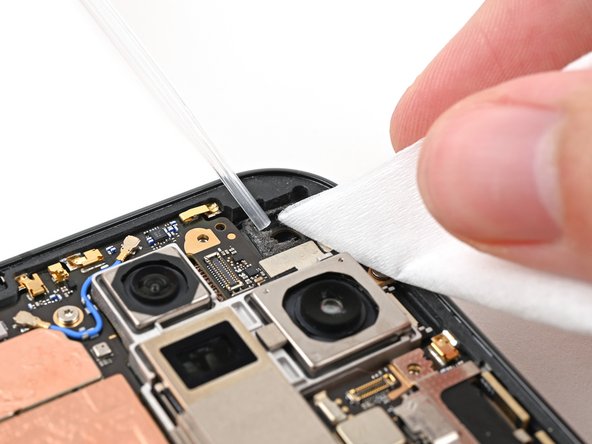
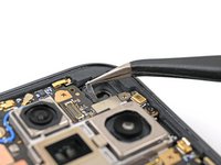
Use tweezers, or your fingers, to remove the old adhesive foam from the inner front camera cutout.
-
Use isopropyl alcohol (>90% or greater) and a coffee filter or lint‑free cloth to remove any adhesive residue.
-
-
-
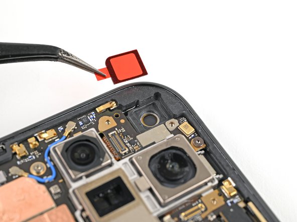
Peel the replacement inner front camera adhesive foam off its clear liner to expose the adhesive underneath.
-
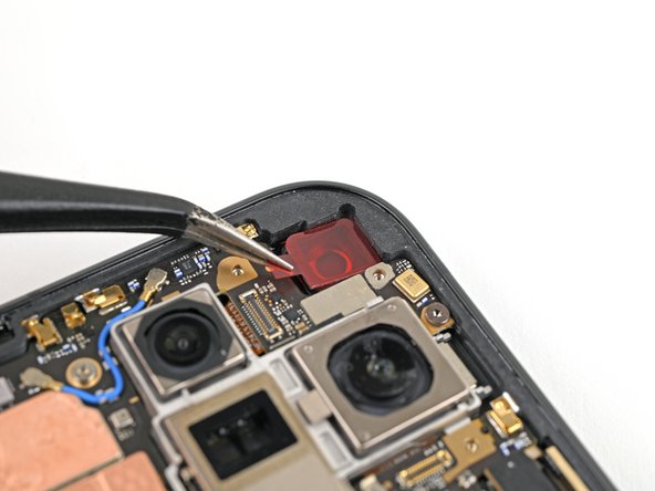
Align the adhesive foam over the cutout in the frame so that the pull tab is facing the bottom of the phone.
-
Place the adhesive in the cutout.
-
-
-
While holding the inner front camera above its cutout, reconnect its press connector.
-
Lay the inner front camera in its cutout and press down to secure it to the adhesive.
-
-
-
Reinsert the inner front camera bracket clip under its slot in the logic board and align the screw holes.
-
-
-
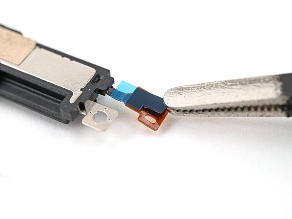
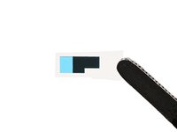
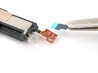
Use tweezers to hold the antenna cable's connector in place over its socket and gently press down with your finger or a spudger until the connector snaps into place.
-
-
-
Place the vibrator bracket on the logic board and align its screw holes.
-
-
-
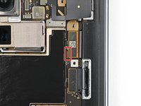
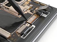
Reconnect the USB-C port board cable press connector.
-
-
-
Reinsert the base battery bracket clip under its slot in the logic board and align its screw holes.
-
-
-
Use a spudger, or your fingers, to remove the old back cover adhesive.
-
Use isopropyl alcohol (>90%) and a coffee filter or a microfiber cloth to remove any adhesive residue.
-
-
-
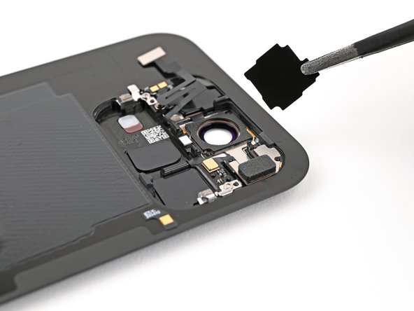
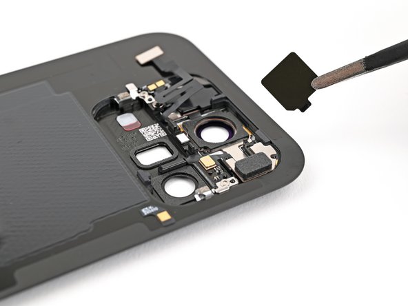
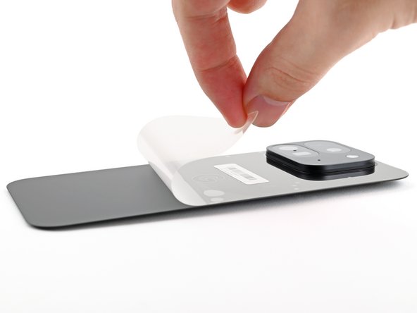
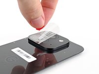
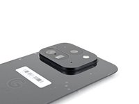
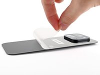
Use tweezers, or your fingers, to remove the three rear camera liners from the inside of your new back cover.
-
-
-
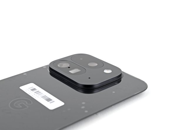
Before removing any liners, check if the adhesive matches the frame.
-
-
-
Peel away the top half of the new adhesive strip from its clear liner and keep it folded before continuing.
-
Align the top half of the adhesive over the frame, using the corners as reference points.
-
Place the adhesive on the frame.
-
-
-
While holding the back cover or propping it up, reconnect the back cover cable.
-
-
-
Reinsert the top bracket clip under its slot in the logic board and align its screw hole.
-
-
-
Use the tip of a spudger to pry up the segmented tab on the top right corner of the secondary liner.
-
-
-
Align the top edge of the back cover with the frame and press down to adhere it.
-


Congratulations on completing your repair!
Take your e-waste to an R2 or e-Stewards certified recycler.
Repair didn’t go as planned? Try some basic troubleshooting, or ask our Google Pixel 9 Pro Fold Answers Community for help.
Congratulations on completing your repair!
Take your e-waste to an R2 or e-Stewards certified recycler.
Repair didn’t go as planned? Try some basic troubleshooting, or ask our Google Pixel 9 Pro Fold Answers Community for help.


1Rehber Yorum
Deleted my earlier comments, after reviewing this again I can see it's not too bad. Reinstalling all the adhesive kind of scared me at first but its all included in the kit.