Bu sürüm, hatalı düzenlemeler içerebilir. En son doğrulanmış bellek kopyası dönün.
Neye ihtiyacın var
-
Bu adım çevrilmemiş. Çevrilmesine yardım edin
-
Remove the following ten screws:
-
Two 8 mm 5-point Pentalobe screws
-
Eight 2.5 mm 5-point Pentalobe screws
-
-
Bu adım çevrilmemiş. Çevrilmesine yardım edin
-
Wedge your fingers between the display and the lower case and pull upward to pop the lower case off the Air.
-
-
Bu adım çevrilmemiş. Çevrilmesine yardım edin
-
Use the flat end of a spudger to pry both short sides of the battery connector upward to disconnect it from its socket on the logic board.
-
Bend the battery cable slightly away from the logic board so the connector will not accidentally contact its socket.
-
-
Bu adım çevrilmemiş. Çevrilmesine yardım edin
-
Remove the single 2.9 mm T5 Torx screw securing the SSD to the logic board.
-
-
Bu adım çevrilmemiş. Çevrilmesine yardım edin
-
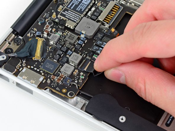
Use a spudger to help lift the free end of the SSD just enough to grab it with your other hand.
-
Pull the drive straight out of its socket and remove it from the logic board.
-
-
Bu adım çevrilmemiş. Çevrilmesine yardım edin
-
Use the flat end of a spudger to pry the I/O board cable up from its socket on the I/O board.
-
-
Bu adım çevrilmemiş. Çevrilmesine yardım edin
-
Peel the I/O board cable up from the adhesive securing it to the fan.
-
-
Bu adım çevrilmemiş. Çevrilmesine yardım edin
-
Use the flat end of a spudger to lift the I/O board connector up and out of its socket on the logic board
-
Remove the I/O board cable.
-
-
Bu adım çevrilmemiş. Çevrilmesine yardım edin
-
Use the tip of a spudger to carefully flip up the retaining flap on the fan cable ZIF socket.
-
-
Bu adım çevrilmemiş. Çevrilmesine yardım edin
-
Remove the following three screws securing the fan to the upper case:
-
Two 5.2 mm T5 Torx screws
-
One 3.6 mm T5 Torx screw
-
-
-
Bu adım çevrilmemiş. Çevrilmesine yardım edin
-
Lift the fan out of the upper case and carefully pull the fan ribbon cable out of its socket as you remove it from the Air.
-
-
Bu adım çevrilmemiş. Çevrilmesine yardım edin
-
Remove the following five screws securing the battery to the upper case:
-
Two 5.2 mm T5 Torx screws
-
One 6 mm T5 Torx screw
-
Two 2.6 mm T5 Torx screws
-
-
Bu adım çevrilmemiş. Çevrilmesine yardım edin
-
Lift the battery from its edge nearest the logic board and remove it from the upper case.
-
-
Bu adım çevrilmemiş. Çevrilmesine yardım edin
-
Use the flat end of a spudger to free the adhesive loop securing the I/O board power cable to the upper case.
-
Disconnect the I/O board by pulling the power cable away from its socket on the logic board.
-
-
Bu adım çevrilmemiş. Çevrilmesine yardım edin
-
Use the tip of a spudger to flip up the retaining flap on the keyboard backlight ribbon cable ZIF socket.
-
Pull the keyboard backlight ribbon cable out of its socket.
-
-
Bu adım çevrilmemiş. Çevrilmesine yardım edin
-
Use the tip of a spudger or your fingernail to flip up the retaining flap on the trackpad ribbon cable ZIF socket.
-
Pull the trackpad ribbon cable straight out of its socket toward the front edge of the Air.
-
-
Bu adım çevrilmemiş. Çevrilmesine yardım edin
-
Use the tip of a spudger to de-route the right speaker cable from the slot cut into the logic board.
-
-
Bu adım çevrilmemiş. Çevrilmesine yardım edin
-
Use the flat end of a spudger to pry the right speaker cable connector up and out of its socket on the logic board.
-
-
Bu adım çevrilmemiş. Çevrilmesine yardım edin
-
Gently push the tip of a spudger under the black plastic flap stuck to the display data cable lock to make the lock pop upward and away from the socket.
-
Remove the small rubber gasket from the corner of the upper case near the display data cable.
-
-
Bu adım çevrilmemiş. Çevrilmesine yardım edin
-
While holding the lock away from the socket, gently pull the display data cable out of its socket.
-
-
Bu adım çevrilmemiş. Çevrilmesine yardım edin
-
Use the flat end of a spudger to pry both antenna cable connectors up and off their sockets on the AirPort/Bluetooth card.
-
-
Bu adım çevrilmemiş. Çevrilmesine yardım edin
-
Gently de-route the antenna cables from the slot cut into the logic board.
-
-
Bu adım çevrilmemiş. Çevrilmesine yardım edin
-
Remove the three 3.6 mm T5 Torx screws securing the logic board to the upper case.
-
-
Bu adım çevrilmemiş. Çevrilmesine yardım edin
-
Gently lift the logic board assembly out of the upper case, minding the fragile heat sink and any cables that may get caught.
-
-
Bu adım çevrilmemiş. Çevrilmesine yardım edin
-
Remove the single 2.9 mm T5 Torx screw securing the AirPort/Bluetooth card to the logic board.
-
-
Bu adım çevrilmemiş. Çevrilmesine yardım edin
-
Slightly lift the free end of the AirPort/Bluetooth board and pull it out of its socket on the logic board.
-
Remove the AirPort/Bluetooth board from the logic board.
-
-
Bu adım çevrilmemiş. Çevrilmesine yardım edin
-
Remove the four 2.5 mm T5 Torx screws securing the heat sink to the logic board.
-
-
Bu adım çevrilmemiş. Çevrilmesine yardım edin
-
Remove the heat sink from the logic board.
-
Logic board remains.
-


İptal et: Bu kılavuzu tamamlamadım.
26 farklı kişi bu kılavuzu tamamladı.

2 Yorum
I concur this does not match the A1465 board in some areas. The Airport / Bluetooth connectors are in a different spot and the heatsink is different. Perhaps some photos from another board were used in a few places. The rest appears to be the same, so far.