Giriş
If you use a power adapter which is to weak for your Mac Book (e.g. 60W for a MBP 15" which is specified for a 80W power adapter) the following should happen from a theoretical point of view: The power adapter is overloaded and heats up until the internal thermal protection switches it off savely. -- And this happened in real live: The adapter blew up in a way, that it delivered one last powerful current pulse which also destroyed parts of the logic board. The Mac Book is still fully operational with battery, but can not be charged nor powered any more, even with a new power adapter.
The disassembling steps are referenced to MacBook Pro 15" Unibody Mid 2010 Logic Board Replacement. For this particular guide it is not necessary to unmount the fans, heatpipes and speaker-microphone-block. Just skip the related steps.
Since the topology of the circuit between power connector and battery is common technique, this guide might fit to other logic boards too.
Neye ihtiyacın var
-
-
Remove the following ten screws securing the lower case to the upper case:
-
Three 13.5 mm (14.1 mm) Phillips screws.
-
Seven 3 mm Phillips screws.
-
-
-
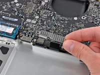
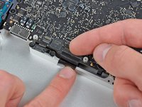
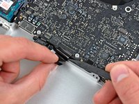
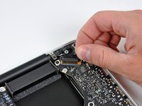
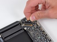
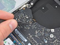
Remove the three T6 Torx screws securing the right fan to the upper case.
-
-
-
-
The picture shows a schematic which is similar to Mac Book Pro's power input circuit. The series components L1, F1, T1, T2 have to draw the full power, so those are of interest for us. With an ohmmeter you can check these parts.
-
L1: Since I could not figure out the manufacturer of this common mode choke I recommend to use a new MagSafe PCB.
-
F1: According to the printing on this part it is very likely that this is a Littelfuse 0469006 6A fuse.
-
T1, T2: Both MOSFETs are HAT1128R type. Since this part is obsolete I took IRF9317PbF
-
-
-
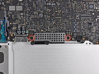
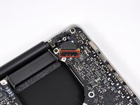
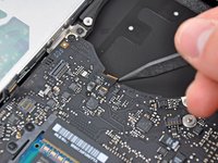
The picture shows where the relevant parts are placed on the logic board. F1, T1 and T2 are marked green. L1 is mounted on the MagSafe PCB and so not seen on the picture.
-
After you have figured out which of these parts (L1, F1, T2, T2) are defective you can change them. I recommend to replace both MOSFETs if there is at least one damaged.
-
After replacing the defective parts you can check the functionality by connecting the battery and the power adapter to the logic board. If everything is fine the LED of the MagSafe connector will light up green and switch to orange if battery will be charged. Be very careful.
-


To reassemble your device, follow the prerequisited guide in reverse order.
To reassemble your device, follow the prerequisited guide in reverse order.
İptal et: Bu kılavuzu tamamlamadım.
17 farklı kişi bu kılavuzu tamamladı.
7Kılavuz Yorumları
I don't know if any 80w MagSafe. It should be 85w for 15" and 60w for 13"...
Great post! Thank you!
I can’t find T1 and T2. My board is little different from the picture . Mine’s 2011 or 12 i7 processor. Please help!
Admirable ! and the pics can be enlarged a lot ! thank you!