Giriş
Use this guide to replace your Samsung Galaxy S4 display assembly.
Neye ihtiyacın var
Videoya Genel Bakış
-
-
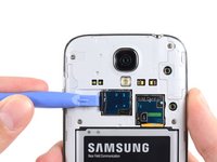
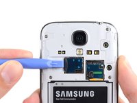
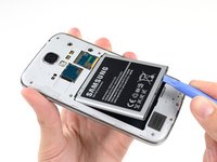
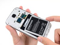
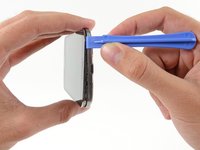
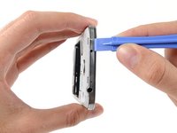
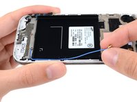
Pry with a plastic opening tool, or your fingernail, in the divot to the left of the rear-facing camera, near the power button.
-
-
-
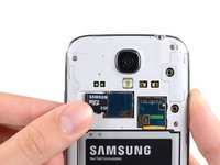
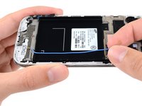
Lift the rear case by the corner nearest the divot and remove it from the phone.
I purchased a blue plastic opening tool(AKA: Spudge) like the one used in the above Step 1 rear cover pic and found the divot and was able to take off the rear cover as per the “Step 2 “ instructions.
-
-
-
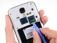
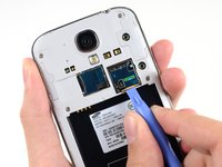
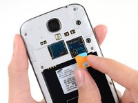
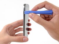
Use the flat end of a spudger, or your fingernail, to press the microSD card slightly deeper into its slot until you hear a click.
-
After the click, release the card and it will pop out of its slot.
-
Remove the microSD card.
I was able to remove the MicroSD Card as per the Step 3 MicroSD instructions with no problems.
-
-
-
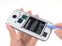
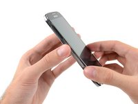
Insert a plastic opening tool, or your finger, into the notch of the battery compartment and lift the battery upward.
-
Remove the battery from your phone.
-
-
-
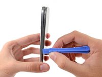
Use a plastic opening tool, or your fingernail, to press the SIM card slightly deeper into its slot until you hear a click.
-
After the click, release the card and it will pop out of its slot.
-
Remove the SIM card.
Looks easy but doesn't work. No one has a plastic opening tool. Using fingernail, you can press SIM card into slot but it does not pop out so you can remove it.
I agree with the comment above
I also don't have a plastic tool and my finger nail won't pop the card out.
Grethe Montano. September 22
-
-
-
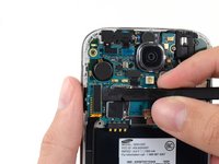
Remove the nine 4.0 mm Phillips #00 screws securing the midframe to the display assembly.
How much cost will be on replace a midframe
I purchased a 1.5x40mm Phillips screw driver and was able to remove all 9 40mm screws from the midframe as per the Step 6 Midframe instructions.
-
-
-
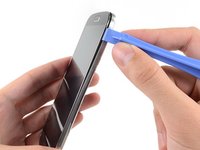
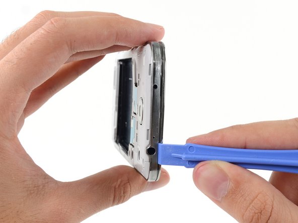
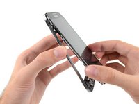
Starting on the volume button side of the phone, insert your plastic opening tool between the chrome bezel around the display glass and the larger chrome border piece. Look for the seam between the two.
-
Slide the opening tool along the seam, separating the plastic clips as you go.
I used same tool as in the photo and i broke the display. I think you should use a very thin plastic tool, such as a credit card but even more thin and flexible.
I purchased a blue plastic opening tool(AKA: Spudger) and was able to remove the midframe from the display assembly as per the Step 7. I had to hold the cell phone firmly in my left hand while I gently forced the spudger between the chrome bezel and the midframe with my right hand and heard plastics clips separate and saw the midframe start to separate from the display assembly. Don’t be afraid to get that spudger in and just gently go down the side of the phone and you will hear the plastics clips detach and the midframe to separate more and more until you are able to separate them 100%. I started at the volume button side of the phone in Step 7 and ended at the power button side in Step 9.
-
-
-
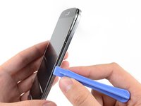
Continue prying around the corner of the phone.
-
Slide your opening tool along the seam between the midframe and display along the bottom of the device, releasing more of the plastic clips.
I purchased a blue plastic opening tool(AKA: Spudger) and was able to remove the midframe from the display assembly as per the Step 7. I had to hold the cell phone firmly in my left hand while I gently forced the spudger between the chrome bezel and the midframe with my right hand and heard plastics clips separate and saw the midframe start to separate from the display assembly. Don’t be afraid to get that spudger in and just gently go down the side of the phone and you will hear the plastics clips detach and the midframe to separate more and more until you are able to separate them 100%. I started at the volume button side of the phone in Step 7 and ended at the power button side in Step 9.
-
-
-
Continue sliding the opening tool around the top of the phone, releasing the last of the clips and freeing the midframe from the display assembly.
On my phone, there was another clip holding the white midframe to the battery compartment, in the middle of the top edge of the battery compartment, near the battery contacts. If you don't release that before removing the midframe, it is easy to break.
I purchased a blue plastic opening tool(AKA: Spudger) and was able to remove the midframe from the display assembly as per the Step 7. I had to hold the cell phone firmly in my left hand while I gently forced the spudger between the chrome bezel and the midframe with my right hand and heard plastics clips separate and saw the midframe start to separate from the display assembly. Don’t be afraid to get that spudger in and just gently go down the side of the phone and you will hear the plastics clips detach and the midframe to separate more and more until you are able to separate them 100%. I started at the volume button side of the phone in Step 7 and ended at the power button side in Step 9. In Step 10 just make sure all the plastic clips are separated from the midframe and the display assembly so you can pull them apart 100% without breaking them.
-
-
-
-
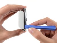
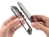
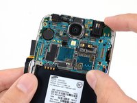
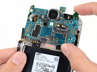
Remove the midframe from the display assembly.
My Sprint S4 was slightly different then the one pictured above but I just completed this repair in under 10 minutes.. It would have been slightly quicker but fooling around with those little screws can be irritating if you have big hands.
-
-
-
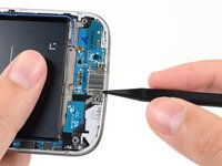
Use the flat end of a spudger to disconnect the USB board connector.
-
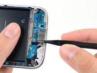
Disconnect the front-facing camera cable connector.
-
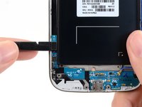
Disconnect the earpiece speaker assembly cable connector.
-
-
-
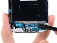
Disconnect the headphone jack assembly cable connector.
-
Disconnect the display/digitizer cable connector.
-
Disconnect the antenna cable connector.
My model had an antenna connection next to the usb board connector in addition to the antenna connection near the display cable connector.
That's point a, on the daughter board (where the USB is located is point b. You must connect it from a to b
I could not get the screen connector to fit on with the motherboard assembly in place. I had to remove the motherboard assembly, attach the screen connector, and then carefully replace the motherboard assembly, with the screen connector still attached..
Same as Tom4G above. When trying to connect the screen connector, it would not give me that nice clear snap indicating a positive connection. The phone powered up with no screen. So, I disconnected the other connectors again, lifted the motherboard out and connected the screen connector by pinching it with finger and thumb from both sides of the motherboard, this time getting a nice snap when it engaged.
speedrzr -
-
-
-
Remove the single 2.4 mm Phillips #00 screw securing the headphone jack assembly to the display assembly.
-
-
-
Remove the headphone jack assembly.
I had a quick question there's a little white rubber circular gasket piece that the headphone jack covers up
What's that piece called?
The small rectangular milky-white silicon gasket appears to be a diffuser for ambient light sensor. I removed it with a small screwdriver, and replaced it in the same location in my new screen assembly.
The small rectangular milky-white silicon gasket appears to be a diffuser for an ambient light sensor. I prised it out of the old assembly and placed it in the new screen assembly. I also started transferring the components as they were removed from the old screen, so the head-phone jack went straight into the new at this point. I may regret that later…
The angle of the picture here makes it appear like the head phone jack needs to be slid out of the top of the phone. This is impossible due to small bits of plastic holding it in at the top. If you're having trouble, the headphone jack is in fact supposed to lift straight up out of the phone.
Additionally, there might be a small amount of adhesive holding the headphone jack to the board (there was some in my device). Apply a bit of heat to loosen it up, if needed.
it is easy to pop off, if you apply pressure to the right point. Using a plastic pair of tweezers or a pry tool, push at the lower right corner and gradually increase the pressure, if you apply enough pressure it will just pop right off.
-
-
-
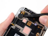
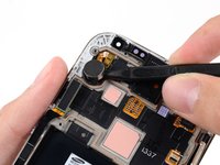
If present, remove the 2.4 mm PH #00 screw securing the upper display assembly bracket.
-
Remove the upper display assembly bracket from the display.
I’ve found that a pretty easy way of popping the bracket off is to slide a thin end of the spudger from the left, then delicately push in - it just popped off easily in my case.
-
-
-
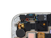
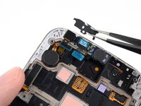
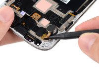
Insert the tip of a spudger under the vibrator to free it from the adhesive holding it to the display assembly.
-
Use the tip of a spudger to pry the vibrator cable up from the display assembly.
bro i cant get it out with a spupger and a i dont have a heat gun/hair dryer any more tips
-
-
-
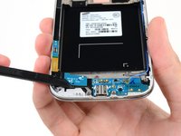
Gently insert the point of a spudger between the USB port and the USB port bracket to pry one side of the bracket off of its post.
Use a tiny screwdriver to pry up next to the left post of the USB port bracket instead of the spudger and it will pop right off. I tried the spudger but it didn't work for me.
-
-
-
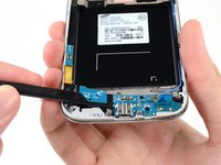
Gently insert the flat end of a spudger beneath the USB board to free it from the adhesive holding it in place.
I also had the most trouble with this part -- it's very well-glued to the assembly, so I used my hair dryer to loosen it somewhat and pried it up with tweezers. This seems to be the part most likely to crack (because it's long and glued down the entire length of the board), so I recommend patience and a little heat to help things along.
I’ve found that applying the heat loosens up the adhesive, making it easier to remove the board.
You can either use a heat gun on lowest setting, or a hair dryer, to apply heat to the board area, then start slowly from the left side. Adhesive appears to be applied as a strip of materials, so with enough care, you can keep it in place and for keeping the USB board in place after reassembly.
Double-sided tape was used in the i9500 version I used. Be very slow. Heat from a hair dryer helped.
Working on Verizon SCH-i545, if you’ll follow the instructions, they really do help. The board will bend ever so slightly because your spudger is crafted at an angle by default. The key is to roll it out, and literally keep the spudger as close to the frame as possible. I removed mine with no heat application. I’ll update this once the repair is completed to let you know how the overall process was and what galaxy diags say once the phone is back together. #StrivelinkTech
Repair went well, hardware working as desired. Used a B stock part to replace the screen since it’s a beater phone repair anyway. Board works fine, went back in smoothly with no heat applied.
-
-
-
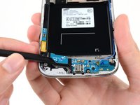
Peel up and remove the antenna connector cable from its channel in the rear of the display assembly.
When did the display get replaced? Is the last piece trash and the phone rebuilt on the new one?
Yep, the component leftover after removing the antenna interconnect cable is the display assembly. The digitizer, LCD and display frame are a glued together unit, replacing the entire assembly is much safer than trying to delaminate the display. The next step would indeed be to rebuild the phone on top of the new display assembly.
-


To reassemble your device, follow these instructions in reverse order.
To reassemble your device, follow these instructions in reverse order.
İptal et: Bu kılavuzu tamamlamadım.
597 farklı kişi bu kılavuzu tamamladı.


28Kılavuz Yorumları
HELP! step 28 just ends how do I insert the new one, how do I resemble the parts that used adhesives to stick?
Nearly all the guides end like this, you just need to work backwards through the steps using the new hardware.
Just work backwards like Nick stated. I usually reverse assemble the parts I take off so I know the order in which I need to put them back in.
Just run it along its track. Use a plastic spudger to push it down. Use 3m double sided adhesive tape to re-attach parts that require adhesive.
What is the difference between an AT&T digitizer and a Verizon digitizer? How interchangeable are they?
I believe the digitizer is the same but if you buy the digitizer with assembly (frame) there is a difference between the models. Here are the model numbers for all the versions. I545 (Verizon) , I337 (AT&T), L720 (Sprint), M919 (T-Mobile), I9500 (International), i9505 (International)
The "display assembly" I purchased was very simple: glass and LCD and a small board with cable and that's it. It didn't have all this beefy mid frame stuff so I had to reuse my old one. Check to see which part you purchased before going through unnecessary disassembly steps like I did.
When you get to Step 7, it is much safer (for the screen) to begin to separate the mid frame from the seam inside the battery compartment. Place the phone face down on a clean sheet of paper, put your fingernail in the seam and pull it apart with spudger. Much less likely to do any damage to the screen.
Help, i replaced the display assembly, but the touchscreen isn't working. any idea of what i've done wrong? or did maybe damaged something?
This just happened to me too, I think I might have pulled the digitizer by mistake or took off the sticker on the back which might have messed up the ribbon cables, did you fix it yet? My touch screen isn't working now also.
justin -
Absolutely 100% perfect. Everything works and I have my Galaxy S4 back. Couldn't be happier!!!
Thanks SOO MUCH! This was awesome. Just pay close attention to the pictures as you go, take your time, and save yourself about $150 vs having a shop do it...
Further advice: DO NOT use anything metal when prying apart the frame in the beginning... The cell phone tool kits are worth it.
this is the video I should of seen. https://www.youtube.com/watch?v=n5RCwDQP...
I have two phones with the same problem. After reassembly, just before I install the midframe, I check the phone with the sim card and it works perfect. When I install the midframe I get intermittent on one phone and continuous and the other 'sim card not recognized restart the phone'. I get this, as I've said, only when the midframe is re-installed.
Perfect! Great guide, all functions a go.
I have a Verizon Samsung Galaxy S4, and during disassembly I noticed that it contains two antennas - one in the position as shown in this guide and one on the exact opposite side (colored light red). It too must be disconnected in the same fashion as the antenna in this guide. Removal and installation of both antennas was simple. As the guide suggests, I would recommend installing USB board and motherboard back in place prior to reinstall and routing of antenna wires. Excellent guide. Fixed my broken S4!
thank you thank you thank you!!!! i didn't have any of the tools but used my thumb nails!
Easy. Thanks for sharing this tutorial.
Hi i want s4 display no wornty i want
I did it, and it wasn't too hard.
Here are some tips:
- when removing the midframe, begin from the side with the volume buttons like mentioned here
- the USB board can be bent a bit, it will probably still work fine if it did not crack when you removed it.
- The GT-i9515 also uses the GT-i9505 screen
- make sure that all ribbon cables are really fully attached, apply a bit of pressure
- when reattaching the midframe, make sure to clip in the power button side first, you will have a VERY hard time clipping it on there last. I had to remove the midframe again and start at that side
Thanks - Works well
Good walk through.
Thanks for the great, easy instructions iFixit!!!
Great guide, I just did it now for fun, I broke the S4 display in January 2019 and wanted to try to replace the screen. So today I managed it thanks to this guide. The USB board was hard to remove and I bent it like a potato chip, but still works fine. I put the I9505 display part on I9506 and it still works. The plastic mid-frame was super fragile, the places for screws crack easily (even before reassembly) and also the edge broke completely on one place during my re-assembly.