Giriş
Use this guide to replace the Micro-USB port daughterboard.
Neye ihtiyacın var
-
-
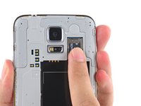
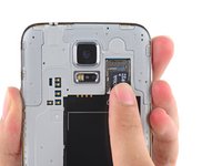
Insert a fingernail or plastic opening tool into the divot to the left of the rear-facing camera.
-
Gently pry and twist the flexible rear cover off the back of the phone.
-
-
-
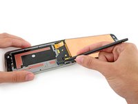
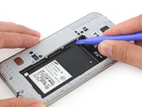
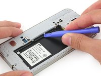
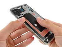
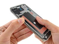
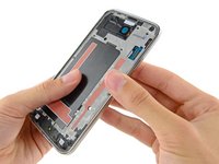
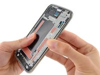
Insert a fingernail or plastic opening tool into the recess in the bottom right corner of the battery and lift upward.
-
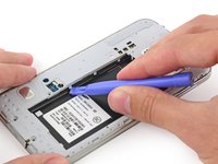
Remove the battery away from the phone.
The battery will need to be charged after it is placed in the phone. No one told me that and I bought a battery and thought it was bad. Keep the phone off and insert the charger. You will need to charge it for several hours before you can use the phone.
-
-
-
Using a fingertip, pull the microSD card straight down out of its slot.
-
Remove the microSD card from the phone.
I found removing the SIM/SD card with my fingertip a little difficult – not enough friction. So I used a 'rubber' (in US English it's called a pencil eraser or just simply, an eraser.
Simple, cheap (zero) and effective! :)
Cheers.
John
-
-
-
Repeat the above procedure to remove the SIM card.
Actually this isn’t as easy as it appears in the photo and instructions, since the SIM card does not have a notch that you can use to pull it out. In my experience I’ve found that the best way to remove the SIM card is by pressing down somewhat hard on the SIM card, and then push-pulling it outward.
-
-
Bu adımda kullanılan alet:Tweezers$4.99
-
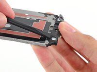
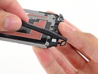
Use a plastic opening tool to pry up the plastic midframe connector panel.
-
Remove the connector panel with a pair of tweezers.
In my experience I have always removed this Home button protector panel with ONLY a plastic opening tool, and I have never found adhesive beneath it.
-
-
-
Place a heated iOpener on the left side of the phone for at least 90 seconds.
-
Reheat the iOpener and place it on the right half of the phone.
good location for a timer, I am taking my phone apart
¿se puede hacer con la pistola de calor?
Si, puedes utilizar la pistola de calor también, pero ten cuidado ;-)
Otra opción es usar una “placa calefactora” que, según yo, es la opción mas “profesional” ya que con ella se puede limitar la temperatura, para que no se malogre la pantalla táctil (la “digitizador” detŕas del vídrio).
Another option is to use a “hot plate” which, according to me, is the more “professional” option since with it you can limit the temperature, so that the touchscreen doesn’t get ruined (the “digitizer” behind the glass).
A hairdryer on low not being used statically is also an easy option. Or if your a caveman or low tech, and all you have is a single baby sock and metal bb’s or little rocks, as long as they’re not silica rocks, put them in the baby sock, at the edge of your cave campfire to warm them and thats all you need. -retired aviation engineer
-
-
-
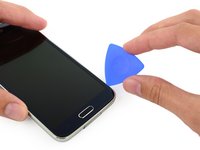
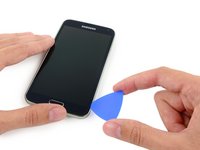
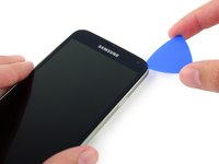
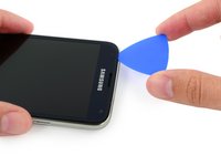
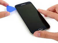
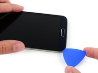
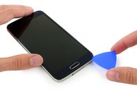
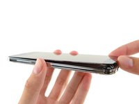
Insert the edge of an opening pick underneath the bottom right side of the front glass.
I hope this helps others:
my screen was STRONGLY glued to the midframe, it was impossible to remove it without breaking it, be very careful with the copper adhesive in the midframe!!!
I can't even understand how this guide doesn't mention it properly!
Yeah, the real trick with these types of screens is to measure (or just “have a feel for”) an adequate temperature with the heat pad (e.g. iOpener), or heat gun, or hot plate. First you have to heat up the screen just enough so that you can “break into” one side without breaking the bezel or the glass, and then verrrry carefully and verrrrry gradually insert plastic opening picks (or even playing cards) as you make progress around the exterior border of the phone. Whenever I do this, I always insert 5-6 objects (again, plastic picks or playing cards) before I fully remove the digitizer-glass assembly, which typically ends up as follows as I move around the exterior border: one pick at each of the four corners and one pick on each of the two sides. WARNING: DO NOT INSERT ANY OBJECT BENEATH THE GLASS MORE THAN A FEW MILLIMETRES FROM THE EXTERIOR BORDER.
Wow seriously 100% ur going to break the LCD if this is the first time opening the phone this is why android is built disposable it now costs 60$ to fix a stupid 10$ part this fix is definitely not worth it
android=disposable
apple=a better way of life
I will never attempt to fix another android again
-
-
-
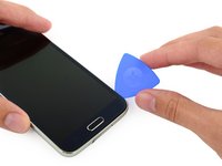
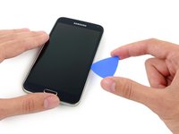
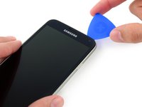
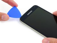
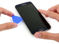
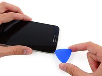
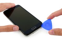
Slide the opening pick up along the right side of the display.
This is not as easy as they make it seem in this guide. The real trick with these types of touchscreens is to properly measure (or just “have a feel for”) an adequate temperature with the heat pad (e.g. iOpener), or heat gun, or hot plate, that you use to heat the adhesive beneath the glass exterior of the digitizer-glass assembly. First you have to heat up the screen just enough so that you can “break into” one side without breaking the bezel or the glass, and then verrrry carefully and verrrrry gradually insert plastic opening picks (or even playing cards) as you make progress around the exterior border of the phone. Whenever I do this, I always insert 5-6 objects (again, plastic picks or playing cards) before I fully remove the digitizer-glass assembly, which typically ends up as follows as I move around the exterior border: one pick at each of the four corners and one pick on each of the two sides. WARNING: DO NOT INSERT ANY OBJECT BENEATH THE GLASS MORE THAN A FEW MILLIMETRES FROM THE EXTERIOR BORDER.
-
-
-
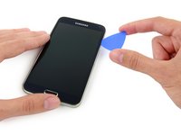
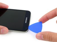
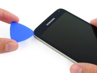
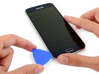
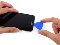
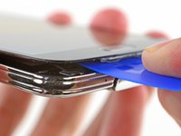
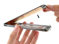
Carefully slide the pick around the corner, stopping before the speaker grille at the top of the phone.
Be sure not to nick and tear the capacitive touch chip interface that meets the LCD screen here! I caught it and didn't even feel the resistance. :-(
-
-
-
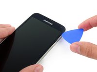
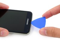
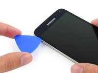
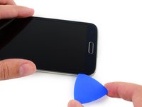
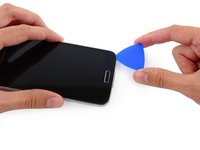
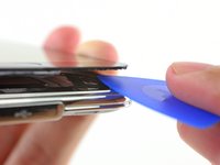
Slide the opening pick across the top of the phone, being very careful not to insert the pick too deeply.
-
-
-
-
Slide the very end of the opening pick across the bottom edge of the display to separate the last of the remaining adhesive.
-
-
-
Twist the opening pick to detach the glass from the phone.
Be aware that there is adhesive on the inner parts of the screen. Plan on replacing this screen and digitizer as well.
-
-
-
Insert an opening pick under the soft button icons on the display and pry the button cables down off the inside of the front panel.
My digitizer was glued to the chasis, the glass came up separately and the digitizer broke when I tried to pry it up.
That’s actually probably because you might not have heated the sides of the screen (where the adhesive is located) enough before prying up on the exterior border of the glass part. It’s very difficult to know the tolerance limits of such devices if you’ve never seen them apart before, and as such one can easily get confused between where the glass ends and the digitizer begins. On my first smartphone repair I broke a digitizer, so I know how it feels.
-
-
-
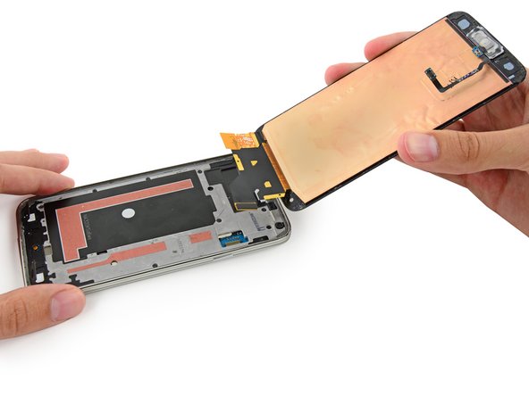
Slightly lift, but do not remove, the home button end of display assembly.
The display assembly I purchased from ifixit.com included a new home button with a new flex cable. If you have the same, I'd recommend removing the home button in this step.
Same here. My home-button flex cable extended under the main board rear cover plate, and would have required removing screws to extract. So I left the original home button installed, and removed the one that came with the new assembly.
The ‘reverse order’ step are misleading. It is not trivial to reconnect the main screen flex cable to the main assembly — lots of trial and error to get it snugly plugged into the receiving connector. That part is glossed over. (Dissassembly is trivial. Reassembly is hard.)
After putting the screen and connectors on, I learned that there’s some plastic edging on the BACK. I had to remove the screen since it effectively wraps the home-button key. The new screen cracked. Great.
Sansumg S5 is the stupiest design (for repair) ever.
I have fixed s2,s3,s4, note, note 2 and note 3
All of them, you can get into the logic board from the back without touching the screen assembly.
With the S5, just a simple problem could cost you buying a new lcd assembly.
You must remove the lcd in order to remove the screws for the logic board cover.
I purchased a cracked lcd S5, so I can replace it and sell it. My mistake was I did not did a research on the tear down (thinking it should the same as previous S model.
To make story short, lucky for me, I did a dry test of the entire phone, before glueing on the new lcd assembly.
Because the front camera lens was damaged, cost $5.
If I glued the lcd, it would be 50/50 chance that I would crack the new screen.
So any repair that you need to do on the S5, you will have to consider the risk of breaking the LCD.
I hope Samsung change the design on the S6. Which I doubt it. Because the higher cost of repair means people won't fix them = more new sells
How can I find out if I messed my phone up . the person who glued the screen on didn't glue it on right , so I tried to take off the screen and I got it off but now that I try to put it back on the screen is black .
I know this reply is a bit late, over 2 years late, but I just wanted to add to idevice Recycle that the way "they" designed this phone is exactly as you described, to make it wayyyy more difficult to fix even the most simplest thing on this phone. Inverting the motherboard, designed exactly the opposite way of the S4 (as you described), from their standpoint of view, as you'd have to admit, was a brilliant idea on "they're" part.
I've torn apart and fixed many cell/smart phones in my days thus far, but mostly iphones by far. A friend passed
me one of these phones this past week. I've never messed with one before so you already know, even though I
have much knowledge about them, this site was the first I visited about this phone. Needless to say, go figure.
They did a really great job though making this phone one of the most difficult phones to do any type of repair
on. Adhesive sucks. But eh, all is well with a bit of time and patience. Had to replace rear camera and middle
bezel frame. Time to off it....
This guide may have been written for a different revision but the SM-G900F that I just repaired had glue sticking the entire of the rear of the screen to the chassis making it very difficult to remove. Had to use a spudger and push it down the inside of the phone separating the copper film from the chassis to free it up. Would be easy to damage the home button cable but I was ok.
I had the same thing happen just now. I was working on a G900A. A real PITA!
mcr4u2 -
Is there a need to put adhesive after removing the screen?? If so, do you have an adhesive recommended...
Should be. i recommend using 3m strip double sided adhesive
leiki42 -
I had the same issue as idevice recycle. The model S5 that I was working on had a huge amount of glue on the back of the lcd which I wasn't aware of - this caused me to crack the glass which then literally broke the lcd in half (costing me £120 for a new screen!!!)
I've repaired all manner of Samsung products over the years and I've never had any issues with any model apart from this one. My advice to anyone doing this repair is once you have managed to unstick the screen from the frame, before attempting to remove it, apply a bit of heat (but not too much, you don't want to damage anything) to the back of the phone where the battery normally sits. This is where all the glue on the back of the lcd is located which sticks the lcd to the frame of the phone - I wish I knew of this before trying to remove the screen!
So this really blows. I needed to swap the logic board from a phone with a cracked screen to one with a good screen. Yeah that’s not happening. I now have two cracked screens… Thanks Samsung! The difficulty on this should be way higher. As others have said, the screen is glued on the underside over a large portion where the copper foil is. It’s not coming up easily or in one piece.
If you want to make the reassembly easier, be careful to not separate the Home button assembly, from the glass. Instead, just carefully pry away the soft button adhesive connectors.
-
-
-
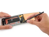
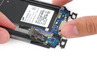
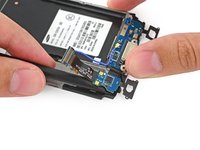
Use the sharp tip of a spudger to lift the front panel assembly cable connector straight up off its socket on the motherboard.
-
Safely remove the front panel assembly from phone.
Absolutely wonderful! Worked like a charm. This is the easiest replacement I have seen so far on an Android. :)
This was all a breeze until I removed the screen and the LCD and digitizer crumpled on me now I have to replace the whole thing not just the charge port which was the initial issue… Great guide though and thanks it helped. Minus the panic attacked when all the parts started to crack and break as I removed the glass and now digitizer or LCD stayed safe for replacement.
The difficulty of changing the S5's display is enormous. Not only is it glued around the edges, it's also glued strongly to the midframe. If you ignore this, damage is inevitable. The digitizer flex cable is also very easy to kill. Glue sucks. When assembling the display, the edge bonding is not enough; you need special double-sided adhesive tape that is stuck to the midframe so that the display does not fall out again so quickly. Before doing this, you have to thoroughly remove the old adhesive on the edge. I have successfully performed this procedure once but would never do it again.
-
-
-
Remove the ten 3.4 mm Phillips #000 screws from the display side of the midframe.
It’s probably a good idea to remove (and subsequently screw back in) these screws in a sort of “star fashion” (e.g. alternating from top-to-bottom, left-to-right) in order to equally distribute the tension.
-
-
-
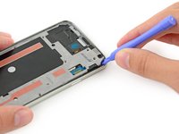
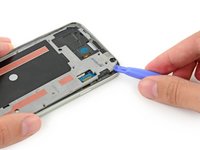
Gently run a plastic opening tool down along the left inner side of the interior frame to separate the three white plastic clips.
There are also two more white clips just along the edges of the battery connection terminals (to the right of the 3 shown in the pictures). Using a spudger to pry these loose too will make separating them later much easier.
Yes, I second that! You definitely need to loosen those two other clips or you may have problems separating this interior frame from the midframe.
-
-
-
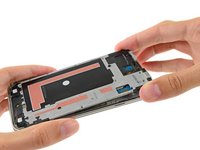
Gently pull the long sides of the silver bezel out away from the phone to separate the two halves of the midframe.
maybe my phone was stuck a little, but i had to work it pretty hard to get this step. Just take your time.
Personally I wouldn’t recommend separating the midframe-motherboard assembly like this. What I recommend is the following: 1. Insert the flat end of a spudger between the main speaker grille and the main camera assembly (technically, between the gray and black plastic pieces. 2. Pry up on the black plastic piece (using the gray plastic piece as a fulcrum) in such a way that allows you to lift that end of the interior midframe-motherboard assembly from the inner midframe (see step 27). THEN 3. Once you have created enough space, insert a triangular pick tool, and THEN use a plastic opening tool to pry any remaining corners out of the silver bezel (see step 26). WARNING: BE VERRRRY CAREFUL WHERE YOU INSERT TOOLS or apply pressure because there are many sensitive components along that top part (where the cameras and infrared sensors are located).
-
-
-
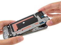
Continue on to the right side of the silver bezel, pulling away from the interior section of the midframe to separate the two halves.
Personally I wouldn’t recommend separating the midframe-motherboard assembly like this. What I recommend is the following: 1. Insert the flat end of a spudger between the main speaker grille and the main camera assembly (technically, between the gray and black plastic pieces. 2. Pry up on the black plastic piece (using the gray plastic piece as a fulcrum) in such a way that allows you to lift that end of the interior midframe-motherboard assembly from the inner midframe (see step 27). THEN 3. Once you have created enough space, insert a triangular pick tool, and THEN use a plastic opening tool to pry any remaining corners out of the silver bezel (see step 26). WARNING: BE VERRRRY CAREFUL WHERE YOU INSERT TOOLS or apply pressure because there are many sensitive components along that top part (where the cameras and infrared sensors are located).
-
-
-
Carefully remove the interior midframe/motherboard assembly from the white inner midframe.
Did two of these phones, and a small white hard plastic cap fell out. Can anyone tell me where this goes on reassembly? See pic: http://library-static.snapfish.com/libra...
The white plastic cap which fell out is actually the piece that covers a small hole marked R2 near the original philips head screw you remove when first disconnecting the small display connector. The good news is that this cap can be put back on after fully reassembling the phone.
-
-
-
Carefully wedge the tip of a spudger underneath the antenna cable connector.
-
Delicately lift the spudger directly upwards to disconnect the antenna connector off its socket on the motherboard.
Same and all so in the s5 I disassembled there was 2 antenna cables the a blue one and a white one.
I also had 2 cables - a blue and a white one.
I second that: At least with the G900-V, there are two antenna cables, a blue one and a white one, .WARNING: Although each cable is of a unique length, you MUST remember or note which cable is connected to which socket, otherwise reassembly will be impossible.
-
-
-
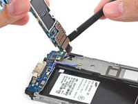
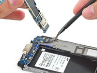
Use the flat end of a spudger to carefully peel the soft button cables up off the interior midframe.
Could someone explain the whole LED, softbutton, cable thing please. Are the white things LEDs or capacitive sensors. Do they stay stuck to the board or to the cable, when removing the daubo ? I’ve seen it both ways.
I believe that the white parts that you see, which act as the physical representation of the soft buttons, serve as both capacitive sensors AND LEDs. The photos from steps 32-35 are actually incomplete, since they don’t describe well how to properly handle these buttons. Since most of these micro-USB daughterboard assemblies come with the soft button sensor-LEDs already built-in to the assembly, once you use the flat end of a spudger to peel the soft button cables up from the interior midframe, I recommend that you go one step further and then ALSO completely remove all remains of the current soft button assemblies (the black adhesive and the white sensor-LEDs) from both plastic bezels of the midframe. That way, you can be sure that what you install with the new daughterboard is all new, ruling out any potential future problems or incompatibilities with the old parts.
-
-
-
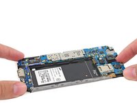
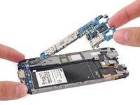
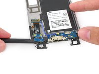
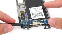
Rotate the midframe/motherboard assembly and reinsert the spudger between the daughterboard and interior midframe.
-
Twist the spudger to separate the last of the adhesive between the daughterboard and interior midframe.
-
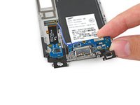
Remove the daughterboard from the interior midframe.
Steps 32-35 are actually incomplete, since they don’t describe well how to properly handle the soft button assemblies. Since most of these micro-USB daughterboard assemblies come with the soft button sensor-LEDs already built-in to the assembly, once you use the flat end of a spudger to peel the soft button cables up from the interior midframe, I recommend that you go one step further and then ALSO completely remove all remains of the current soft button assemblies (the black adhesive and the white sensor-LEDs) from both plastic bezels of the midframe. That way, you can be sure that what you install with the new daughterboard is all new, ruling out any potential future problems or incompatibilities with the old parts.
Thanks Niko! Totally would have been confused by that. Probably would have just layed the new LEDs on top and messed things up. >.<
It might also be worthwhile to mention that the paint beneath the glue here is extremely fragile due to the solvents present in the glue - not that it isn’t pretty fragile elsewhere as well - and that some extra care ought to be taken as you’re next to an LED. To put it another way: If you get the edge of a spudger into the paint (trying to pick up that last glob of goo) it will act like a reverse magic marker and unexpectedly pick up an unexpectedly wide line of black paint. I suggest tweezers for that last little bit.
-


To reassemble your device, follow these instructions in reverse order.
To reassemble your device, follow these instructions in reverse order.
İptal et: Bu kılavuzu tamamlamadım.
176 farklı kişi bu kılavuzu tamamladı.


40Kılavuz Yorumları
Since replacing the part I cannot register on the network, Wifi works, cellular says full signal but selected network unavailable. Sim works in another phone and another sim doesn't work in this phone.
Adam -
Make sure you reatach the tiny connector that was taken off in step 28. That is crucial to reception and can easily fail to click into place. It seems very likely that that is the problem.
Adam, did you make sure you replaced with the exact same model?
my apple -
This guide needs to be changed to Difficult. Removing the screen without breaking it will be challenging. If you are successful after that, the rest is easy.
Very, very hard
Wish I’d read the comments before starting. Just broke my screen. despite heating it and trying to be careful. Extremely disappointed.
Be sure to buy the same revision charging port you are replacing ,if you dont do this you would experiment signal issues,
Also many charging ports of this (ebay,alibaba or whetever you get them) come with bad microphone or even dont charge!
So full test before sticking the lcd again!
The lack of reception will probably be due to mismatched versions of the board......
Check the printing on the board for a 'REV' version number......If this number doesn't match, you will more than likely end up with signal issues.....newer replacement boards *might* be backwards compatible with older original boards, but to the best of my knowledge, forwards compatibility does not exist.......
Your best option would be to source an identical REV version board.
I have run into this EXACT problem with a couple of Samsung devices, and have even created a guide about it on the S2 forum over on XDA.......
I just replaced the daughterboard rev 0.7 with a rev 0.8 and everything works perfectly! Just make sure the black antenna cable is tucked away behind the plastic border. Else it might come loose when you snap the daughterboard in place. Phone was a Galaxy S5 Neo.
Great guide!!! Although I have a couple notes: I might have a newer version of the phone:I also had the white cable that isn't shown or listed in this guide.I used the same technique as the blue cable-anybody completing this guide can do the same.Something I did on accident to be wary of is that when using a plastic prying tool on Steps 25-27, I bent in the volume rocker leads and when I reassembled they wouldn't work.Had to take the phone apart again and test, carefully bending them back upward with the pointed end of the spudger. Everything was fine after reassembly.One final note--the pictures are great, but a complete before macro photo of necessary phone parts would be amazing-I couldn't tell in the pictures if leads were supposed to be bent upwards--the rest seemed to be all lapped over in that fashion so I felt I was really taking a risk--if I had a macro of the motherboard at 45 degrees I'd have been able to see that it was supposed to be bent upward. Otherwise, amazing guide and many thanks!!!
By reading these comments..I'm just gonna not try to fix the charging port..good thing I have warranty or I can just upgrade.
Love this Step by Step BIY for S5. Sadly, i dont have $$ for the parts or time. I give this a 5
Does anyone know if some Samsung models would have compatible charging ports? or any good places to purchase charging ports?
I have the Model G900W and can't find a new charging port anywhere
After replacing charging port my rear camera is taking pictures in pink.. help asap
Step 29 .
Need the power switch cable adjacent to the sim holder.
There are three pin bends and two of them are damaged in my phone.
Everything is perfect in my mobile but couldn't switch it on?
Can i find it online. If yes please provide me the link. I'm from India.
If no, please let me know the next whole product i should buy to make my phone work.
Thanks.
I severed the ribbon to my recent app button and it is no longer working. Would replacing this daughter board make my recent button work again?
Yes it would.
oi pessoal tenho um galaxy s5 coloquei ele na agua e comecou a ter problemas de sinal wifi qnd chegar em uma carga de 40% ele fica saindo da rede depois que coloquei na agua quero trocar essa entrada usb dele pra tentar resolver esse problema estou em amsterdam teria algum SITE bom que eu conseguiria comprar por aqui!? welbeton@hotmail.com
When removing the soft key flex cables one of the small white (LED?) pieces came up and the black adhesive is all mangled. What are the little white squares? should they be connected to something? I haven't been able to find them anywhere and they aren't shown with the replacement daughterboards I have looked at either. I am planning to replace the mid frame as well as the daughterboard so do I need to peel the white squares off and stick them to the new frame? Thanks.
For the note 3 device:
What about the screen's adhesive? Do I have to hurry so the adhesive will still be warm enough not to become solid again? Am I supposed to somehow reapply adhesive before completing the assembly?
I bought several Boards on eBay. Every board hat the same problems:
Button's go crazy when i am using mobile data?
Does anyone noticed similar problems?
What are the reasons for which people usually change the micro USB daughter board?
Just replaced the port REV 08 with REV 06 and the buttons work but it's not charging. Could this be the issue?
I replaced a rev8 board with a rev6 and it does not charge. The USB won’t even get recognised by the PC. I also have a blue and a white antenna cable. Mine is a S5 (LTE?) SM-G901F UK EE. I also get no 3/4G signal. I put the old one back in and all works (except loose connector, which is why I was replacing it)
After fitting a new daughterboard, it all works apart from the two capacitive buttons. The daughterboard, as purchased, has some white things in the little black touch cables. It’s not clear what these are, and whether they replace the ones that are already there. Are they LEDs ? They look like some looped pcb track. How much am I supposed to peel the little white tabs of the touch-button tails after purchase ?
This is rediculous just to replace the charging port. On top of that you have to make sure you are replacing it with one compatible with your version of S5. A great phone to use but not worth this trouble! Better to just get another S5 since they are so cheap now. Or get a wireless charging sticker for the back cover and accept slower charging.
Success! Many thanks to Niko for the helpful commenting. :) My foil was damaged, but everything else was intact. Charges like a champ now!
is it possible to change a charging system for S5 that have a cracked screen and reassemble as before or there will be a need to completely change the screen
i chanche the charging port but it still doesn’t charge. What’s the problem?