Giriş
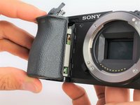
Warning: The flash capacitors located under the front grip contain dangerous amounts of stored charge and will need to be safely discharged before removing the motherboard. Use a Capacitor Discharging Tool to do so.
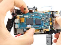
The motherboard is crucial for the function of both the software and hardware of the Sony a6500 camera; its failure will result in an inoperable device. If your camera is failing to turn on despite having a functional battery, the motherboard may need replacing. This guide will walk you through the replacement of the motherboard; it requires more steps than the other guides because it is embedded deep inside the camera. This guide will require opening tools, spudger, tweezers, JIS 0 screwdriver, JIS 00 screwdriver, and JIS 000 screwdriver.
Neye ihtiyacın var
-
-
-
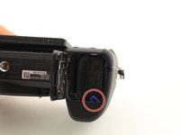
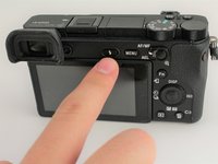
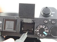
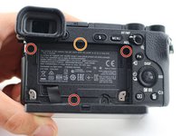
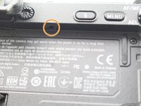
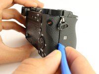
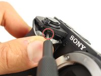
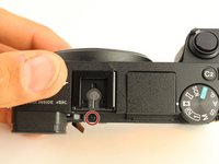
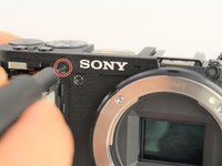
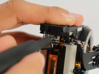
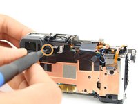
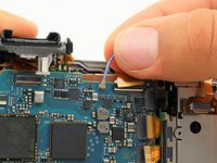
From the top of the camera remove one 4mm JIS 00 screw.
-
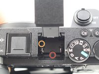
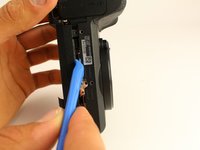
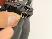
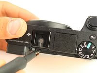
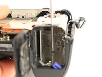
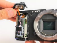
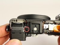
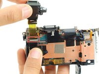
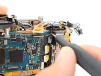
Remove one 5mm JIS 00 screw and the plastic bushing around it.
-
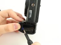
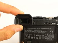
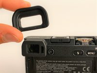
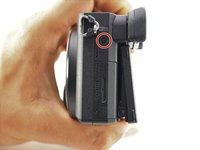
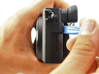
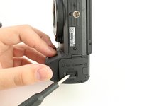
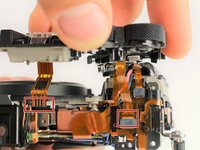
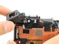
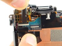
Remove the viewfinder's protective cover.
-
-
-
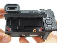
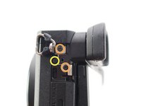
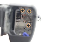
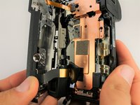
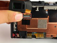
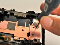
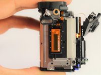
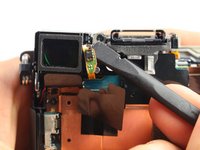
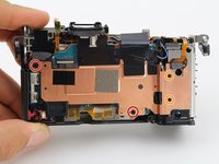
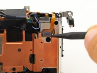
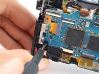
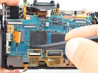
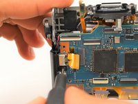
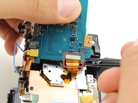
Remove two 2.5mm JIS 00 screws from the left side and bottom of the copper shielding.
-
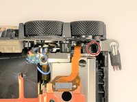
Remove two 2mm JIS 000 screws from the right side of the copper shielding.
-
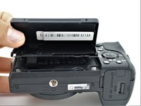
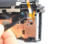
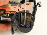
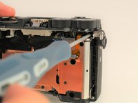
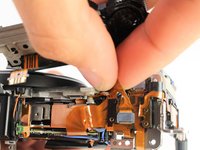
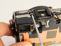
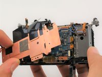
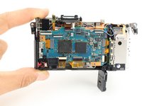
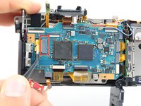
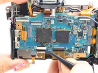
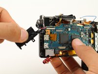
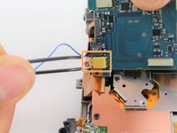
Pull the entire copper shielding piece off.
-


To reassemble your device, follow these instructions in reverse order.
To reassemble your device, follow these instructions in reverse order.
İptal et: Bu kılavuzu tamamlamadım.
6 farklı kişi bu kılavuzu tamamladı.

Ekip

Cal Poly, Team S11-G5, Regan Fall 2019 Cal Poly, Team S11-G5, Regan Fall 2019 üyesi
CPSU-REGAN-F19S11G5
5 Üyeler
14 adet Kılavuz yazıldı