Ana içeriğe geç

Weinmann VENTImotion and VENTIlogic Control Board Replacement

Tıbbi Ekipman
iFixit de, bu onarım kılavuzu da tıbbi cihaz üreticisi tarafından onaylanmış değildir ya da herhangi birinin üreticiyle alâkası yoktur.

Neye ihtiyacın var

  1. Weinmann VENTImotion and VENTIlogic Control Board Replacement, Control Board: adım 1, 1 resimden 1.
    • Open the device

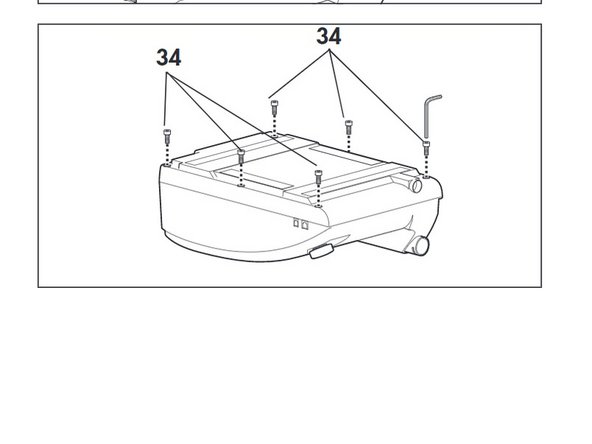
    • 1) Place the device on a non-slip surface with the top facing downwards.

    • 2) Remove the filter cassette from the top part of the housing.

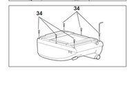
    • 3) Undo and remove the 6 screws (34)
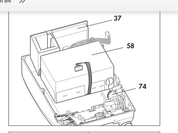
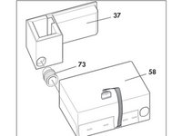
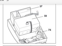
  2. Weinmann VENTImotion and VENTIlogic Control Board Replacement: adım 3, 1 resimden 1.
    • Disconnect the following

    • - encoder connector (82)

    • -connectors of interfaces (84) and (85) of the control board.

  3. Weinmann VENTImotion and VENTIlogic Control Board Replacement: adım 4, 1 resimden 1.
    • Disconnect the ribbon cable of the display and the fascia film:

    • Pull the latch out until you feel resistance. You can then pull out the ribbon cable.

    • If the latch has not been opened correctly, the ribbon cable may be damaged when it is pulled out.

  4. Weinmann VENTImotion and VENTIlogic Control Board Replacement: adım 5, 1 resimden 1.
    • Pull flow measurement hoses (56) off the flow sensor.

  5. Weinmann VENTImotion and VENTIlogic Control Board Replacement: adım 6, 1 resimden 1.
    • Pull pressure measurement hoses (57) off the pressure sensors.

  6. Weinmann VENTImotion and VENTIlogic Control Board Replacement: adım 7, 1 resimden 1.
    • Insert a new battery (52) in the appropriate holder of the new control board

    • Screw on spring (54)

  7. Weinmann VENTImotion and VENTIlogic Control Board Replacement: adım 8, 1 resimden 1.
    • Put the control board in the top part of the housing and attach it with the four screws (51)

  8. Weinmann VENTImotion and VENTIlogic Control Board Replacement: adım 9, 1 resimden 1.
    • Reattach the pressure measurement hoses (57) to the pressure sensors.

    • Connect the flow sensor marked Hi to the hose connector marked Hi at the device outlet.

  9. Weinmann VENTImotion and VENTIlogic Control Board Replacement: adım 10, 1 resimden 1.
    • Attach the flow measurement hoses (56) to the flow sensor

    • Connect the connection of the flow sensor marked Lo to the hose connector marked Lo at the device outlet.

  10. Weinmann VENTImotion and VENTIlogic Control Board Replacement: adım 11, 1 resimden 1.
    • To prevent the hoses from kinking, position flow measurement hoses (56) and pressure measurement hoses (57) as shown.

  11. Weinmann VENTImotion and VENTIlogic Control Board Replacement: adım 12, 1 resimden 1.
    • Connect the ribbon cable for the fascia film and the display to the control board again:

    • –pull the latch upwards.

    • –push the ribbon cable into the connector.

    • –press the latch back down

  12. Weinmann VENTImotion and VENTIlogic Control Board Replacement: adım 13, 1 resimden 1.
    • Plug the connectors of the interfaces and the rotary knob into the appropriate slots of the control board.

  13. Weinmann VENTImotion and VENTIlogic Control Board Replacement: adım 14, 2 resimden 1. Weinmann VENTImotion and VENTIlogic Control Board Replacement: adım 14, 2 resimden 2.
    • Refit the box and filter holder.

    • Connect the box and the filter holder to one another by reconnecting the intake side hose (73) from both parts.

    • Refit box (58) and filter holder (37) back on the top part of the housing together.

    • Connect the pressure-side hose (74) from the box.

  14. Weinmann VENTImotion and VENTIlogic Control Board Replacement: adım 16, 2 resimden 1. Weinmann VENTImotion and VENTIlogic Control Board Replacement: adım 16, 2 resimden 2.
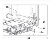
    • Close the Device: Hold the bottom part of the housing (35) up to the side of the top part of the housing (36)

    • Plug the connecting cables for the humidifier (42) and the alarm (43) onto the relevant connectors.

    • Check that all hoses and cables are plugged on firmly.

    • Place the bottom part of the housing (35) on the top part of the housing (36). Ensure that no cables or hoses are trapped or bent.

    • Now screw the top part of the housing tight using the 6 screws (34).

    • Then turn the device back over

    • Check contrast and adjust if necessary .

    • Reset the date and time.

    • Set the date as follows: Year, Month, Day

Sonuç

To reassemble your device, follow these instructions in reverse order.

Bir başkası bu kılavuzu tamamladı.

Jay Vidinoff

Üyelik tarihi: 04/07/20

610 İtibar

2 adet Kılavuz yazıldı

Ekip

Cal Poly, Team S7-G19, Paton Spring 2020 Cal Poly, Team S7-G19, Paton Spring 2020 üyesi

CPSU-PATON-S20S7G19

3 Üyeler

4 adet Kılavuz yazıldı

0 Yorum

Yorum Ekle

İstatistikleri Görüntüle:

Son 24 Saat: 0

Son 7 gün: 0

Son 30 gün: 1

Her zaman: 137