Giriş
This guide will help you to replace the LCD display. For this replacement, you will need to use a #00 Phillips screwdriver and a small tri-point (Y) screwdriver.
Neye ihtiyacın var
Videoya Genel Bakış
-
-
Place Gamepad face down and remove the two 4.7 mm screws with a Phillips size #00 screwdriver.
-
-
-
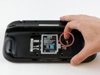
With your finger, press down and pull back on the battery connector plug.
-
Remove the battery from the battery case.
-
-
-
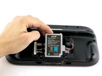
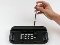
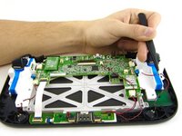
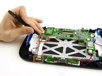
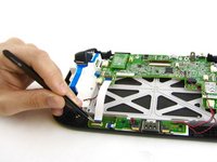
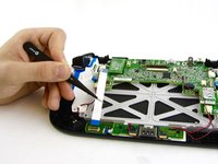
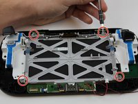
Remove 10 9mm screws with Tri-Wing size Y1 screwdriver around the outer case.
-
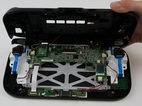
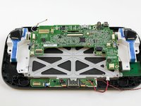
Lift up on the back of case.
-
-
-
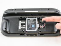
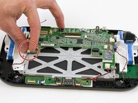
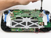
Unplug outer case rumble motor connector from the motherboard with your fingers.
I agree. A circle over the plug would have been better as the picture looks like you just pull on the wires lol.
Chris -
Thanks for the comment. I did get a set of tweezers and the negative cable broke anyway. They really could have done a better job at using a different connector for that.
Why in the world is this thing so tightly connected?
Thanks for the comment. I did get a set of tweezers to try to pull it out but still ended up breaking the negative cable. They really could have used a better set of cables and connectors for this.
You don’t have to do this step!!!! Just open the switch while keeping this wire intact!!!!!
-
-
-
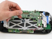
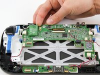
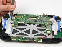
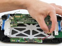
With your fingers, unplug the left speaker cable from the motherboard.
Speakers are connected with solder so removing them is not possible without requiring soldering later on. I left them both connected and instead of removing the motherboard completely I just "hinged" it carefully down to facilitate the work following step 18.
Thank you for offering this info because I spent 20 minutes between scratching my head and searching for any alternatives to just the image above, which had a wire nut/housing (and mine certainly did not). As I began to have an anxiety attack (
Mine also did not have connectors for the speaker. But like mentioned above, I was able to do repair WITHOUT the need to unsolder the speaker wires. Thanks!
-
-
Bu adımda kullanılan alet:Tweezers$4.99
-
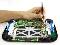
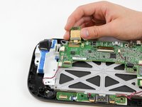
Remove the right speaker cable that's connected to the motherboard with the tweezers.
Note that on some units (presumably later ones), the speakers are soldered onto the motherboard.
-
-
-
Bu adımda kullanılan alet:Tweezers$4.99
-
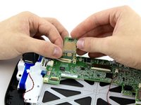
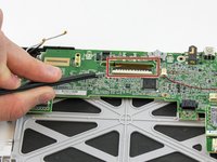
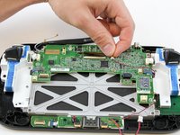
Open the top and bottom clasp that connects the white flex cable to the motherboard with the tweezer.
-
Remove the white flex cable with the tweezers.
Attention! You have to flip up gently the small plastic cap on top of the ribbon connector. Do not try to slide the plastic cap horizontally. This method holds for all ribbon connectors.
Isn’t it WiFi?
-
-
-
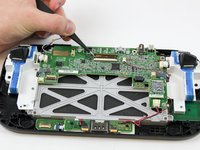
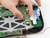
With your fingers, lift and remove Wi-Fi board.
These little boards (Bluetooth and NFC) have a small connector but also have double sided tape holding them down. So you may need to apply more force than expected to remove these due to the tape.
Isn’t it Wi-Fi?
-
-
-
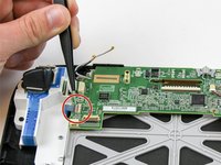
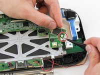
Disconnect the black and white wires off of the back of the Wi-Fi module.
One important thing to note here is how the black and white wires are routed to the board. You should take a picture since if you do not route these the same way, the wires can interfere with the button or get trapped when you assemble the case back possible blocking a screw hole.
Isn’t it Wi-Fi?
Any idea what the name of the white wire is? I accidentally broke through mine.. having trouble finding a replacement
-
-
-
Lift and remove the Wi-Fi module.
Isn’t it Wi-Fi?
Does it really matter?
Thanks a lot for the guide. I just fixed my gamepad and it appears to be working good. Just one question: why do you include the step in which you remove the flatflex cable to the other pcb? It seems unnecesary
-
-
Bu adımda kullanılan alet:Tweezers$4.99
-
Disconnect the analog connector with tweezers.
There was a little tab on the top of the male end of the connectors that I had to push to get them out.
Take a small flat head screw driver and push out and to the left on top of the white part of the connector. If you try to use tweezers on this model it will not come out.
-
-
-
Remove the blue connector using tweezers.
Looks like there are 2 of these connectors - left and right side
Lift the little gray tab before you pull the blue ribbon out.
-
-
-
Carefully lift the black clasp. It is prone to breaking if only lifted from one point. Remove the brown ribbon by using the tweezers.
-
Unclasp and release the small digitizer ribbon cable to the left of the brown ribbon.
The small connector is the digitizer (touch senor panel) - The large connector is the actual display
For the small connector, lift up the black part on top from this side.
I broke that small connector (the lid) how can I fix that? The flex is still goes there but I won't get touch response unless I apply some pressure to it!
if you fixed it, can you tell me how did you do it?
Bast -
The small grey ribbon has a clasp holding it down. It needs to be opened in the opposite direction of the black clasp on the wide ribbon before you disconnect the ribbon.
-
-
-
Remove the small orange ribbon with the tweezers.
These tiny connectors are difficult to see how to manipulate. Similar to other ribbon connectors, there is a lever that flips up to release the ribbon cable. However, unlike the larger connectors, the lever flips up from the opposite side that the connector enters. Run your tweezers up the back side of the connector body, and the grey top should flip to vertical. Then the ribbon cable will slide out.
This small connector is attached to the screen as well.
What do I do if I broke off the gray top cover that went over the wire things.
You probably don’t need this anymore, but that happened to me a while ago and now i’m gonna have to buy a new motherboard. Your motherboard is as good as done for
The Boi -
Snapped it off too. Tried hot glue.with no luck. Does anyone know if Motherboard s are interchangeable? I have Version B
Foe Suar -
-
-
-
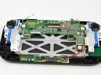
Remove the remaining three 5.1 mm screws using the Phillips size #0 screwdriver.
-
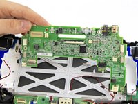
Lift and remove the mother board.
There's a 4th 5.1mm screw along the bottom edge in the middle.
The speakers were soldered as mentioned above, so I carefully folded the motherboard down to facilitate work
-
-
-
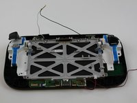
Remove the four 5.1mm screws using Phillips size #0 screwdriver.
-
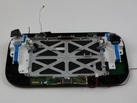
Pull the white and black cables away from the display case.
-
-
-
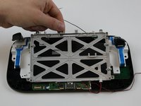
Lift and remove the grey display case with your fingers.
There are two more screws under the sync component that requires you to disconnect the board and remove it as well. These screws prevent you from lifting out the display case as noted in step 19
-
-
-
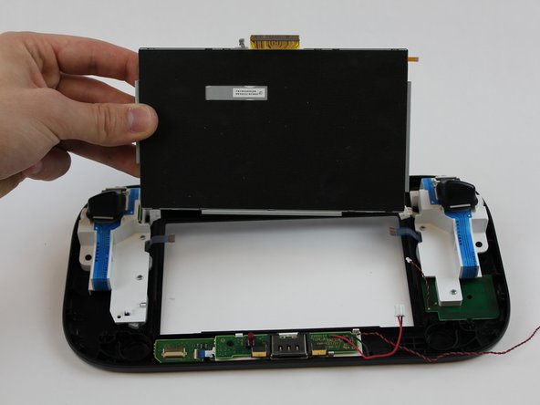
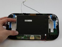
Gently with your fingers, press on the front of the display and it will lift up.
-
Remove the display with your fingers.
There is a black plastic trim ring on the front of the screen, on top of the digitizer. While not technically required to it does provide a barrier to crud getting under the edges of the screen and also looks better. It is stuck down with adhesive or double sided tape. You can slowly and gently pry it up from the digitizer, remove the old adhesive and re-stick it down with double-sided scotch tape on the new digitizer. This is possible to do after you have everything re-assembled but is much easier to do BEFORE you reassemble. Just align it to the inside edges of the screen.
If you have two separate parts for your replacement, the LCD and the Digitizer, the digitizer usually has some adhesive on it, so you can stick it down onto the LCD. Make sure to remove all the protective films!
Could have mentioned the trim ring in the guide...
If there are two of a connector, say something please. Steps 12 and 13 only mention and show the left one, and I ended up tugging my motherboard up with the right ones still connected.
-


To reassemble your device, follow these instructions in reverse order.
To reassemble your device, follow these instructions in reverse order.
İptal et: Bu kılavuzu tamamlamadım.
83 farklı kişi bu kılavuzu tamamladı.
Ekip

USF Tampa, Team 1-6, Sullivan Spring 2016 USF Tampa, Team 1-6, Sullivan Spring 2016 üyesi
USFT-SULLIVAN-S16S1G6
4 Üyeler
40 adet Kılavuz yazıldı
18Kılavuz Yorumları
was really perfect to repair my device. Thank you very much for this help
In step 14 - what does the small gray ribbon do? The replacement LCD display that I got in the mail did not have it.
Its the touch screen cable. The screen I ordered did not come with one. I had to carefully remove it from my broken display and put it on the new one. Thankfully the touchscreen still works for me.
Mine did not come with the touch screen either.
I replaced the digitizer, as well as the LCD screen. My replacement digitizer came with the wide orange ribbon; however, the tiny touchscreen ribbon is actually orange and fused onto the LCD display (the original was gray and located on the digitizer, not the LCD screen).
Thank you for this guide! Worked awesome repairing my device. I can add that if you are just replacing a broken screen, the digitizer (if not broken as well) can be removed from the broken (original) LCD screen very carefully, and re-used on the replacement. I took a gamble and only ordered the LCD part replacement but you can get both, or each separately. My is working perfectly and the LCD had been cracked badly. I appreciated the comments from various users on this article as well, pointing out the few things that were missed or not detailed! Still an excellent guide!
My screen was not as bright but all worked on the controller. Anyone else have that issue?
This guide was one the many online tutorials that truly did help me understand how to disassemble my Wii U. I had a digitizer problem so I had to start where I left off here and find another video on Youtube to follow how to switch this piece out. Hint: Each step has comments, make SURE to read those while disassembling. Good Luck
My LCD wouldn’t turn on so I bought one from amazon. Replaced it as per instructions, still completely blank screen. No light at all. Sound is coming from my gamepad, and touchscreen still works.
Hi, I’m going to try to fix my sons gamepad. The touchscreen seems to have stopped working. How would I know what exactly the problem is? Just the touchscreen? Also I’m in Aus, has anyone from here bought a replacement one before?
Replace the digitizer and Lcd. Took awhile connecting everything back up. Compared all the connections with pictures on this site and watched videos. Now the unit will not turn on or charge. Not sure where to even start. Even tried a battery from another unit and no luck.
Can I just mail it to you… and u fix it for me? Lol ?♀️
tried to unscrew the 10 Tri-Wing size Y1 screw with my iFixIt toolkit
unfortunately the tool is too “fat” and short, it cannot reach 4 screws on the corners of the gamepad.
having the iFixIt toolkit and needing to purchase an additional slim screwdriver it’s a shame…
AJtriple - Yanıt