Giriş
Follow the steps in this guide to remove or replace the logic board in a iMac Intel 21.5" EMC 3068.
Some images in this guide use a 2015 iMac, which has minor visual differences. These differences do not affect the repair procedure.
This guide is marked "potentially dangerous" because it requires you to handle a power supply that contains large capacitors. Unplug the iMac and hold the power button down for at least 10 seconds to help discharge the capacitors. Handle the board by the edges and do not touch surface components.
Neye ihtiyacın var
-
Bu adımda kullanılan alet:iMac Intel 21.5" Cardboard Service Wedge$4.99
-
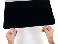
Before beginning any work on your iMac: Unplug the computer and press and hold the power button for ten seconds to discharge the power supply's capacitors.
-
-
Bu adımda kullanılan alet:Plastic Cards$2.99
-
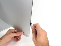
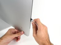
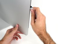
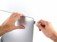
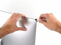
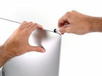
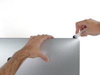
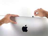
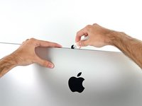
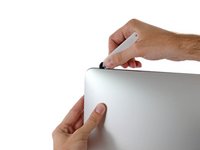
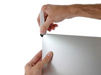
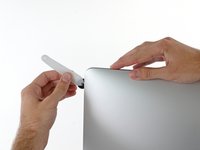
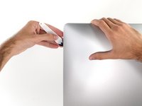
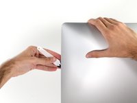
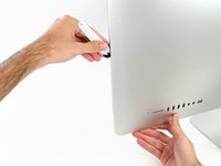
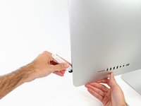
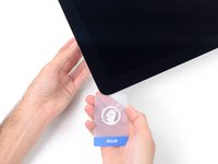
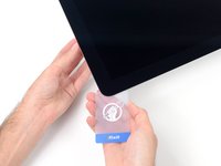
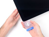
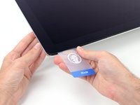
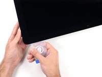
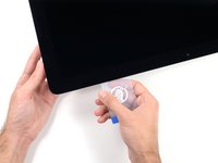
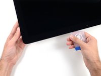
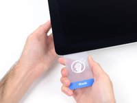
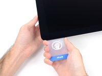
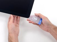
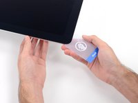
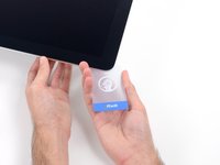
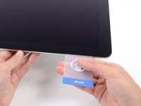
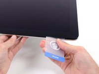
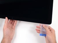
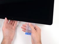
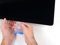
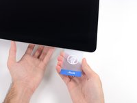
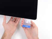
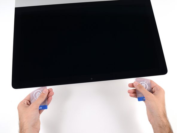
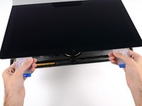
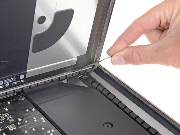
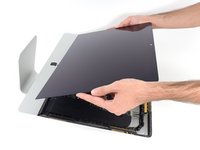
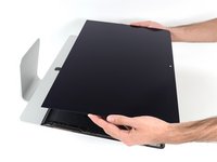
Starting from the top right corner of the iMac, wedge a plastic card between the display and frame.
-
-
-
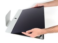
Hold the display with one hand while using your other hand to unplug the display power cable.
-
-
-
Remove the following five Phillips screws holding the lower support bracket in place:
-
Four 3.2 mm screws
-
One 1.7 mm screw
-
-
-
-
Remove the following T10 Torx screws securing the hard drive brackets to the iMac:
-
Two 21 mm screws
-
One 9 mm screw
-
One 27 mm screw
-
-
-
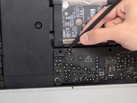
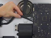
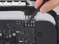
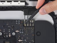
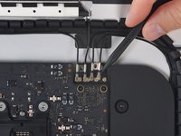
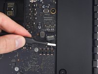
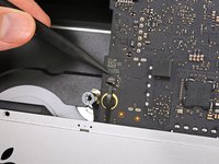
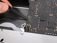
Use the tip of a spudger to push each side of the power button cable connector and gently walk it out of its socket.
-
-
-
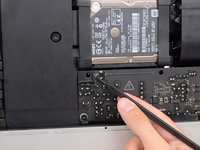
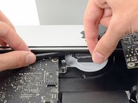
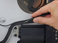
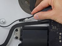
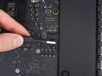
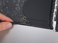
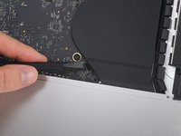
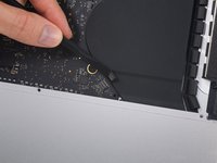
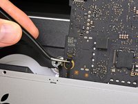
To disconnect the cable, squeeze the release clip on the back side of the connector, behind the logic board, and pull the connector straight out.
-
-
-
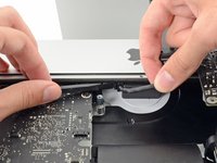
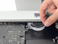
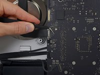
Use the flat end of a spudger to press the release clip on the side of the AC inlet cable connector inward.
-
While pressing on the release clip with the spudger, grasp the AC inlet cable, and pull the connector straight out of its socket.
-
-
-
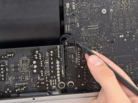
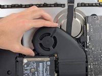
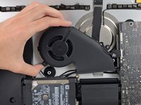
Gently pull the fan cable connector straight out of its socket on the logic board.
-
-
-
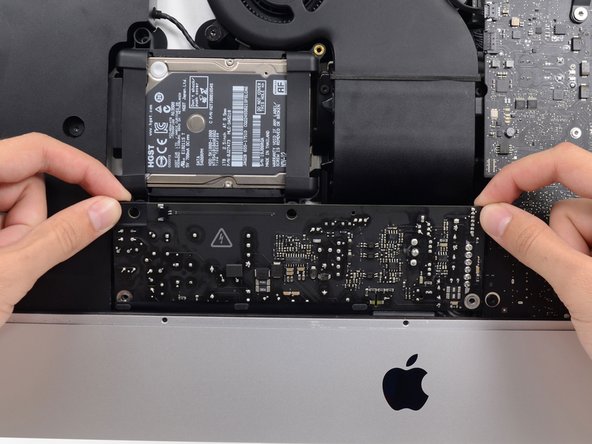
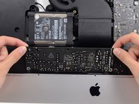
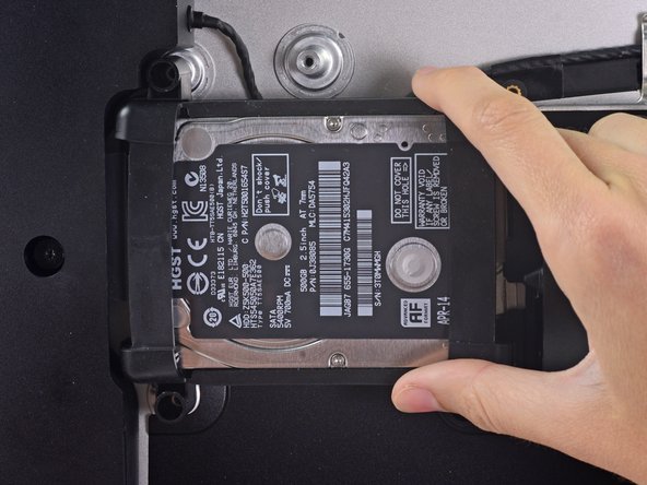
Lift the hard drive from the edge nearest the logic board and pull it slightly out of its recess.
-
-
-
Remove the 7.3 mm T8 Torx screw securing the hard drive tray to the rear enclosure.
-
-
-
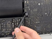
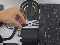
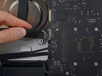
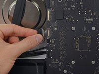
Gently pull the left speaker cable straight out of its socket on the logic board.
-
-
-
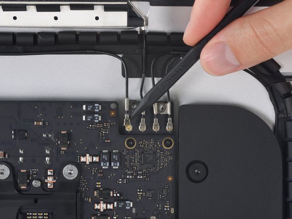
Use the tip of a spudger to flip open the retaining flap on the microphone ribbon cable ZIF socket.
-
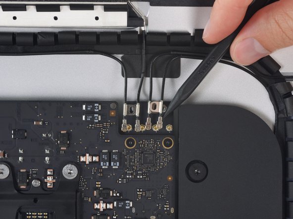
Gently pull the microphone ribbon cable straight out of its socket.
-
-
-
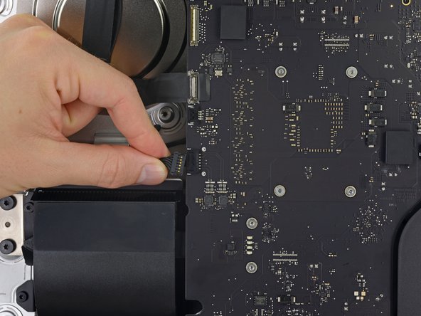
While pressing on the clip with your thumb, lift and disconnect the SATA data connector from its socket on the logic board.
-
-
-
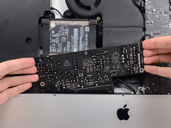
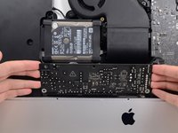
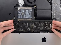
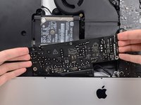
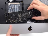
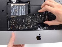
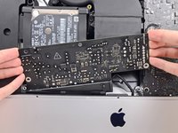
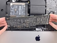
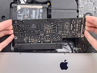
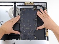
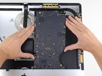
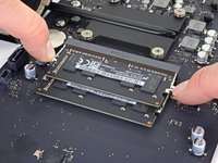
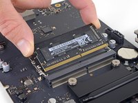
Handling the board by the edges, flip the logic board over to access the two RAM modules.
-
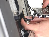
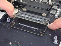
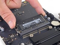
Two clips secure the RAM module in place, one on each side. Using your fingers, spread the clips away from the RAM module.
-
-
-
Remove the two T8 screws from the exhaust port end of the heat sink.
-
Loosen, but do not remove, the four captive T8 screws securing the CPU end of the heat sink.
-
-
-
Remove the two 3.3 mm T5 Torx screws securing the AirPort/Bluetooth card to the logic board.
-
-
-
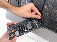
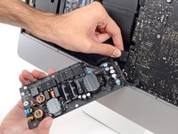
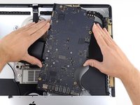
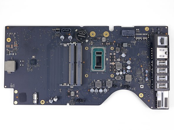
Only the logic board remains.
-
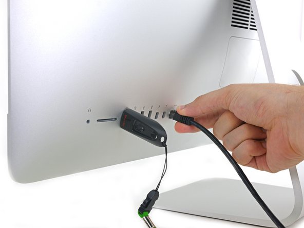
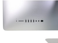
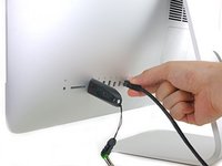
During reassembly of the logic board, pay attention to the position of the I/O connectors. When the board is back in the case, insert a USB or Thunderbolt cable into one of the connectors to align it perfectly.
-


To reassemble your device, follow these instructions in reverse order.
To reassemble your device, follow these instructions in reverse order.

1Rehber Yorum
can I put a new logic board inside say the next step up from the base model to add a dedicated cpu that’s not soldered into the board?