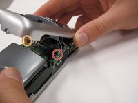
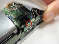
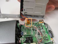
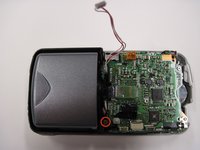
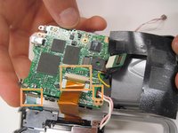
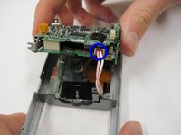
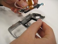
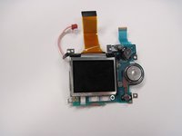
Onarım Kılavuzları
Adım adım kılavuzlarımızla hemen hemen her şeyi nasıl tamir edeceğini öğren.
Cevaplar Forumu
Çözümleri paylaş ve bir arkadaşından yardım al.
Teardown'lar
En yeni cihazların içine göz at.
Haberler
Teknik onarım haberleri için gideceğiniz yer.
Katılın
İnsanlara eşyalarını tekrar çalıştırmalarını öğretmeye yardım et.
Onarım Hakkı
Onarım Hakkı hareketi ve nasıl savunucu olunacağı hakkında bilgi edinin.
Onarılabilirlik
Tamir edilebilir ürünlerin neden makul olduğunu öğrenin.
Manifestomuz
Onarım devrimine katılın!
Öne Çıkarılan
Ömür boyu garantimizle desteklenen kaliteli parça ve aletler.
Aletler
Hassas aletlerden oluşan geniş ürün yelpazemizden satın alın.
Parçalar
Kalite garantimiz ile desteklenen parçalardan alışveriş yapın.
iPhone Bataryaları
Aküler test edilmiş ve garantilidir, ayrıca ihtiyacınız olan her şeyi içeren bir kit.
Cihazların için kılavuz, parça ve yanıtlara hızlı erişim edin
Sökmek
A teardown of the Nikon Coolpix 3500.
4.8
4.9
Bu teardown bir tamir kılavuzu değildir. Nikon Coolpix 3500 cihazınızı onarmak için, servis kılavuzumuzu kullanın.
Remove the battery cover.
Remove the battery.
Remove two 4.5 mm screws next to the battery slot.
Remove one 3 mm screw above the CF memory card slot.
Remove one 4.5 mm screw next to the CF memory card slot.
Remove two 4.5 mm screws from inside the battery slot.
Remove two 5 mm screws from the opposite end of the battery slot.
Remove the plastic cap and the 5 mm screw underneath.
Remove the five 3.5 mm screws from the bottom of the camera.
Gently pry off the grey faceplate.
Do not pull hard; there are two wires connecting the faceplate to the motherboard.
Use a spudger to disconnect the white-capped wire at the bottom of the camera.
Use a spudger to disconnect the orange-capped wire at the bottom of the camera and set the faceplate aside.
Disconnect the grey-capped wires from the motherboard.
Disconnect the blue wire attached to the green chip from the center of the motherboard.
Remove the 3.5 mm screw from the motherboard next to the rotating lens.
Flip the motherboard and lens over to access the three wires on the back that connect to the LED screen.
Disconnect the blue wire connecting the motherboard to the LED screen.
Disconnect the orange wire using a spudger while pushing out horizontally.
Disconnect the red capped wire from the motherboard.
Lift the motherboard and lens (still connected) out of the back case.
Lift up on the black covering and remove the orange wire connecting the lens to the motherboard.
Remove the 2.5 mm screw next to the red capped wire.
Remove the two 3.4 mm screws on the back of the directional buttons.
Remove the two 4.4 mm screws in the metal plate across from the orange wire.
Gently lift the LED screen out of the remaining casing and set it aside.
Be careful not to let the rubber backing of the buttons fall out of place.
10 tane daha katılımcı ile
Üyelik tarihi: 04/19/10
183 İtibar
6 adet Kılavuz yazıldı
Rozetler: 6
+3 tane daha rozet
CPSU-GARNER-S10S30G38
5 Üyeler
11 adet Kılavuz yazıldı
Bu kılavuzu, sitenizin / forumunuzun içine küçük bir parçacık olarak yerleştirmek için, bir boyut seçin ve aşağıdaki kodu kopyalayın.
Son 24 Saat: 1
Son 7 gün: 10
Son 30 gün: 33
Her zaman: 7,856