Giriş
A look inside the ring Stick Up Camera.
Neye ihtiyacın var
-
-
Features:
-
Inside / Outside, Ceiling / Wall Mounting, Quick Release Battery Pack
-
Night Vision
-
Two Way Talk
-
Adjustable Motion Sensors
-
1080p HD Video
-
115° Field of View
-
2.4GHz Wireless B/G/N WiFi Connectivity
-
-
-
Pry off the top cover with the Spudger Tool or a flat head screwdriver. The top cover pad is glued on and may be hard to pry loose. The top cover is thin, so no need to go to deep to pry off top cover
-
Remove the top cover PH00 screws.
-
Pry off the top cover to reveal internal electronic components. The top cover is held in place with an O-Ring.
-
-
-
-
Remove the two screws on either side of the power connector located on the top back of the ring camera enclosure using the PH2 tool.
-
Then using the Spudger Tool, pop of the rubber covers on either side of the power connector cover in the back, and pry off the power connector cover. This will reveal two PH00 screws that hold the external power interface to ring camera enclosure.
-
Remove the two PH00 screws on either side of the external power connector. Then gently using the Spudger Tool pry the external power connector from the ring camera enclosure.
-
-
-
Use the Opening Pick Tool to remove the face from around the ring camera. Insert the Opening Pick Tool between the camera face and ring camera enclosure, and work the Opening Pick Tool around the edges to release the retention clips of the camera faceplate. The Spudger Tool can also be used to pry off the camera faceplate.
-
Remove the four PH00 screws located around the camera face. Once the four PH00 screws have been removed. Use the Spudger Tool to push the camera body loose from the ring camera enclosure. Then remove the camera body from the ring camera enclosure. This will remove the internal metal assembly that hold the camera, and PCBs.
-
-
-
With the camera body removed from the ring camera enclosure, we can do a review of the components that make up the camera body.
-
Light Sensor
-
Camera / Camera Len
-
Multi-Color LED
-
Infrared LED Lights
-
-
-
Turning our attention back to the Main System PCB removed in an early step we can see the following components that are on the backside of the PCB. The PCB is partially conformal coated.
-
-
-
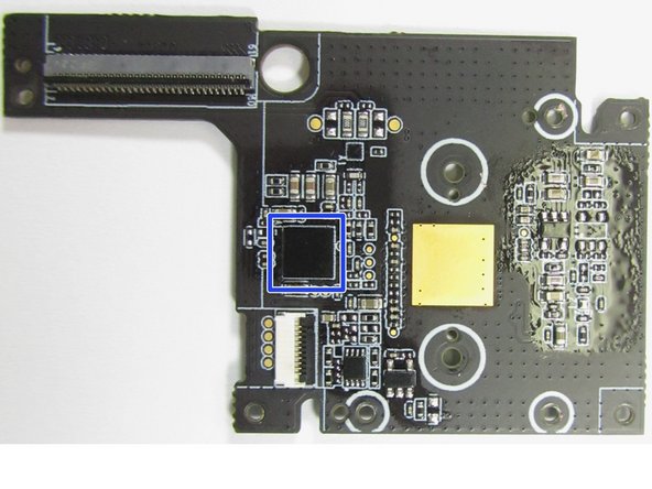
Turning our attention back to the Main System PCB removed in an early step we can see the following components that are on the frontside of the PCB. The PCB is partially conformal coated.
-
ES 5J SEN
-
Nordic N52832 Bluetooth 5/Bluetooth Mesh – Not listed on packaging / Product Specifications
-
-
-
Frontside close up view of the MEMS Microphone.
-
Backside close up view of the MEMS Microphone, which shows the Microphone port.
-
-
-
Close up view of the PIR Sensors
-


8 Yorum
Hello,
very interesting, nice work.
by any chance, do you know what sensor is the Light Sensor ? part number?
thank you.
Thank you so much, so interesting!
This was very helpful. Thank you.