Ana içeriğe geç

2, 2.26, 2.53, or 2.66 GHz Core 2 Duo processor

106 Soru Tümünü görüntüle

Soldering help, making a post

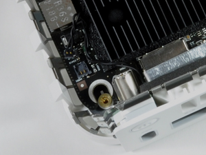
This Mini is the second device where a connector has come off and disabled the whole unit. I can see the two posts on this Mini where the connector broke off. Now I have to raise them or extend them so I have access to solder them back to the power button.

Solder isn’t holding to the nubs of the two wires that went into the traces. Plus it’s almost mcro-micro-soldering. I’m hoping my post here will get some comments about how it might be done.

before

Block Image

after (now)

Block Image

Yanıtlandı! Cevabı görüntüle Ben de bu sorunu yaşıyorum

Bu iyi bir soru mu?

Puan 0
3 Yorum

We really need to see what you are facing. Post some clear hires pics so we can see what you are facing Adding images to an existing question

tarafından

The power button on the mini doesn't close a circuit permanently, just enough to start up. What I really need are the schematics so I can solder elsewhere.

tarafından

Hope these photos are ok. Best I could do. You can barely see the really tiny grey spots. Since I don't have schematics I'm guessing the two on the bottom are the pair I need.

tarafından

Yorum Ekle

1 Cevap

Filtre ölçütü:
Seçilen Çözüm

Ouch! Not the best images but I think I see enough to know you have nothing left on the pads the tan area is the bare board not the copper pads which is why solder won’t stick.

Here’s a better view of the area

Block Image

Apple as far as I know never offered schematics or board views of the Mac Mini series. So finding another location to tap will be difficult without having a reference board which at that point you might as well just replace the logic board. Here’s one source for the replacement logic board TheBookYard UK - Early/Late 2009 Mac Mini Logic Boards

Bu yanıt yardımcı oldu mu?

Puan 2

10 Yorum:

Dan, Thanks. I don't know how to get you directly so this was a hail mary.

I hate Apple doesn't really share. Never has though the ][ was so easy to figure out. I believe Right To Repair goes to all levels...

You're right. Having a reference board I'd just put it in this A1280 and be done with it. However, until my next stimulus comes in and I get the M1 mac mini, this is all I have. Goodwill doesn't see many of these.

The repair question remains. There are points I cqan tell either connect a component or were where the original connector was. But they are flush with the board. Any soldering I've tried won't take.

How can you solder to a flush level point on the board ? Be it a trace (copper) or hole. There has to be a way to connect a wire to those points.

tarafından

As bizarre as it sounds, I could get a dremel tool, make a hole and run a hard point there then attach there. Come to think that's a good last ditch effort lol.m What's the name of a thin point/wire to put into the hole I drill ? Isn't there a real piece like that ?

Yes, it's randomly trying points, but what's the worsst that can happen ? It's already dead.

tarafından

@capwalker666 - Sorry without knowing what the given trace is you're just assuming the line is correct. Drilling or cutting won't do either as again you would only end up damaging other lines.

Logic boards are like a multi layer cake! think of the frosting as copper foils that are sandwiched within the layers as well as on the top and bottom. But unlike our frosting model imagine you have lines of different color frosting in stripes going across and going in a wave! At some points the upper layer color and the one below are the same color and a "Via" hole was drilled and filled with a conductive wire or coating linking the two. Now I'm made a very small example of what a multi layer PCB is like in your mind Now think how difficult it would be to travel across the country by car without a map or any signage or even a compass it would be very difficult! Thats what we face here No idea where in the layers are or where they go!

Sadly, its time to get a new board there just isn't any way you can fix this.

tarafından

@danj around 1983-1984 after I got my apple ][//// certificate I was put into the Epson QX-10 cert track. The only study materials were the schematics and results to expect at test points. Somehow I passed even having little electronics background. It wasn't until the PC and compatible that I went to pure logical (no schematics) troubleshooting. I remember IBM cert in Boca where the instructors simply bent a pin under on memory chips lol. I decided then to study up and got my Ham license. I even went beyond General Class.

tarafından

@danj Them 2 meter got interested in packet radio. Getting an RF modem we could participate in TCP/IP and real internet over the air. I found a package called GRINOS where we had open source internet over the air. Of course you'd have to understand C to modify it.

tarafından

5 tane daha yorum göster

Yorum Ekle

Yanıtını ekle

James Walker sonsuza kadar minnettar olacak.
İstatistikleri Görüntüle:

Son 24 Saat: 0

Son 7 gün: 0

Son 30 gün: 1

Her zaman: 145