
Fairphone 1 Display Assembly Replacement
Giriş
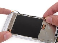
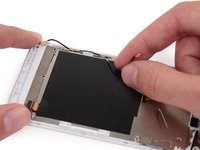
1. adıma gitUse this guide to replace the display assembly, including the LCD screen, front glass and digitizer, on your Fairphone.
Neye ihtiyacın var
Parçalar
Aletler


Daha fazlasını göster…
-
-
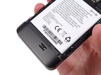
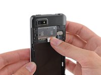
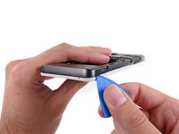
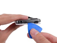
With the indentation as leverage, use your fingernail to pry the bottom portion of the back cover from the phone.
-
-
-
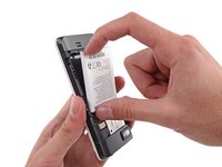
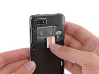
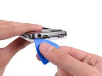
Use a fingernail in this indentation to push the battery toward the top of the phone
-
Pull the battery out away from the phone.
-
-
-
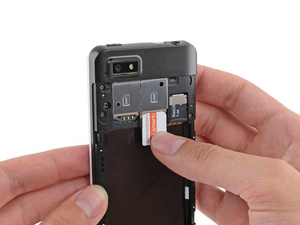
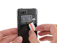
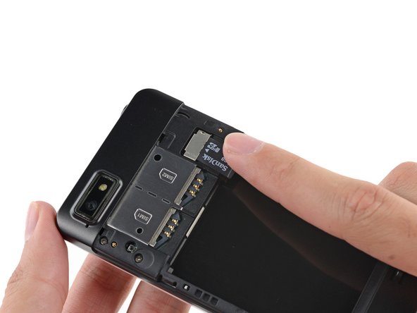
Use your finger to slide the SIM card straight down out of its tray.
-
Remove the SIM card from your Fairphone.
-
-
-
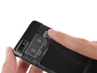
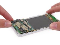
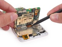
Remove the five 3.9 mm Phillips #000 screws securing the midframe to the display assembly.
The three upper -next to the SIM blocks- screws are a bit longer that the three others. It is important to keep them like this because if not, they will not tight to the whole.
There are only 5 screws. I see none longer than others.
You're right, I've just done it and it's true. Thanks!
Aiala -
-
-
-
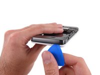
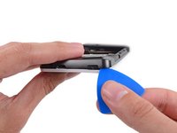
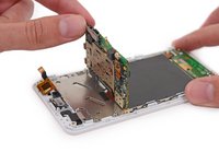
Use an opening pick to carefully pry the midframe away from the display assembly.
-
Start just below the volume rocker and work your way down toward the bottom of the phone, freeing the plastic clips along the side.
Some stupid person put a sticker on the fifth screw. If you can not find the fifth screw, check if there are any BLACK (yes, black) stickers on top of them. Also, which 'designer' made the first design choice for plastic clips? I WILL FIND YOU. AND KILL YOU. *!&*^#% stupidest way to affirm or secure something!
You also can start from the interior (white pieces all around batterie place)
-
-
Bu adımda kullanılan alet:Tweezers$4.99
-
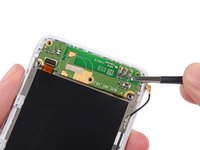
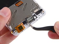
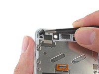
Use tweezers to remove the volume rocker and power buttons from the display assembly.
-
-
-
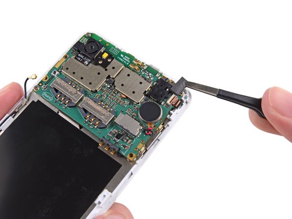
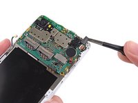
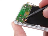
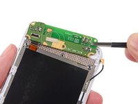
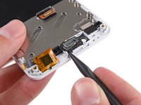
Use the flat end of a spudger to disconnect the antenna cable connector.
Well, I actually broke the socket. Does anyone know if it can be fixed?
thanks
I broke it too, what to do now?
jakob -
What is the thing left of the camera, below the CC \n TC logo printed on the board?
Yep, no need to remove the antenna connectors if you're replacing the display.
-
-
-
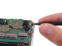
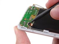
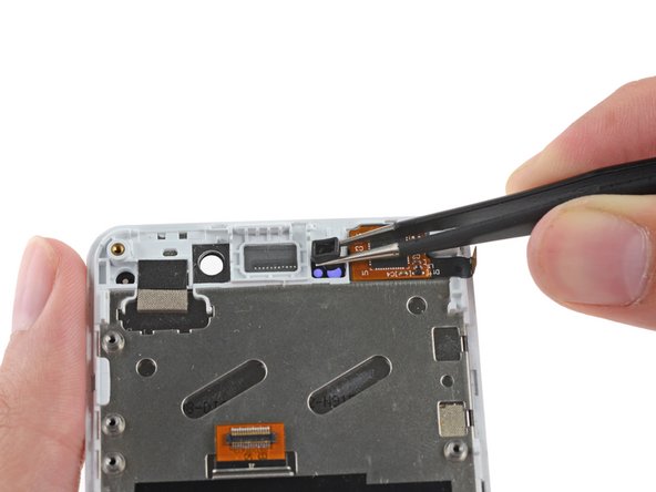
Use tweezers to remove the adhesive foam tape from the top of the digitizer cable ZIF socket.
no adhesive foam on my fairphone
Thank you so much for this amazing tutorial! it works and looks great again!!!
foam tape is black on mine
-
-
-
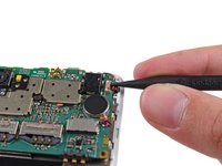
Gently lift the top end of the motherboard up to expose the display data cable.
I had to use a spudger to take off the camera. Not an easy job since it was glued quite well.
"mild" adhesive?? Camera is glued pretty well!
First: English isn't my mothertongue, so please excuse mistakes.
I also lost the camera. But it wasn't a problem. At the end of step 28 it was quiet easier to pry the camera without being careful about the motherboard. Only the reverse was done at step 18 again. I put the camera inside the hole and closed the connector for the data. After that I connected the motherboard again with the display and put all together back. So everything was at its right place.
At the End everything was perfect. I'm as pleased as punch!
This was probably the toughest part. It took it's time to remove the camera from the old assembly. As mentioned in earlier comments, it was glued rather well. Be really careful since there is a data cable connecting the camera to the motherboard, and you won't be able to see it that easily.
I took off the camera with the tweezers and thus I had no problem to remove it.
Possible camera fix after damage while extracting: I too had a well stuck camera, and I damaged the camera while separating it from its small metal plate. The tape holding the plate to the chassis was less strong than the tape affixing the camera to the small plate. The camera seems to consist of a sensor (housed in the silver cube), and its lens (the black plastic bit that separated itself from the cube). The lens is still attached to the sensor by four springy bits of wire which I'm guessing control a magnet which causes the lens to move a bit for focusing. I'm guessing that one of those wires have been damaged and therefor the lens is hanging in its most relaxed state. If you poke the lens carefully with the tip of the spudger you will see that it is kind of swimming in there.
The effect of this is that the lens is stuck in macro mode. Things that are very close will be in focus. A workaround to get the lens to have a fixed focus on around 1 meter to infinity, is to get the lens to push back as deep in the direction of the sensor as possible. This could be accomplished with crazy glue, or similar. I found a rubber washer small enough to not block the lens, which forces it back when the midframe is reattached.
Daniel -
You can actually fix the focus more towards infinity by screwing the inner lens part clockwise.
Lifting the motherboard without breaking the camera module is the most critical step.
I used tweezers to loosen the camera module from the display assembly.
It worked best for me to lift the motherboard slightly (!), so I could see the base of the camera module, and then carefully separate the camera from the metal part that it is glued to.
Have a good lock at the pictures, so you know where the camera module ends and you don't end up breaking the camera module into pieces, instead of taking it off the base.
I had to push the camera module connector back in again, as it came loose slightly.
Everything worked out fine in the end.
-
-
-
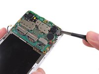
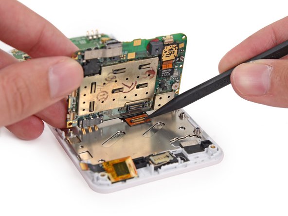
Use the tip of a spudger to disconnect the display data cable from the back of the motherboard.
Yeah, please make sure you don't remove the socket, cause I did it, and after that it's a pain in the !@# to put back. If unfortunatly it happens, remember that the two points on each side of the sockets should be align vertically (from the phone point of view) and the line to the side closer to the phone side.
In my case the camera also stayed glued to the display part. In fact that was no problem - just leave it connected to its metal pad and take both off together (in my case the metal pad was only midly adhesive to the display part). When reassembling just take off the metal pad from the new display and put in place the old metal pad with the camera on.
I reconnected the screen to the motherboard by cutting a small rectangle of cardboard and slide it under the display connector to lift it a little bit. Then you can lay down the mainboard connector on top of it and press it down. It will click in place. Next, slightly lift the topside of the mainboard to remove the cardboard with a pair of tweezers.
-
-
-
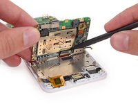
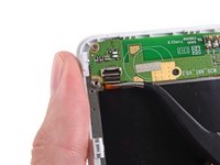
Remove the motherboard from the display assembly.
-
-
-
Use the flat end of a spudger to disconnect the antenna cable connector.
-
-
-
Remove the following screws securing the Wi-Fi daughterboard to the display assembly:
-
Two 2.5 mm Phillips #000 screws
-
One 1.6 mm Phillips #000 screw
No "1.6 mm Phillips #000 screw" in my phone
Not in mine either...
My Fairphone is also lacking the orange marked screw.
Missing in mine too!
-
-
-
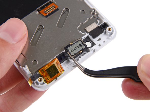
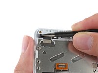
Use the tip of a spudger to gently pry the speaker up from the display assembly.
-
Remove the speaker.
The earpiece speaker may have a 'rubber ring' glued to the front side. The new display assembly will probably have one of these already installed in the earpiece socket, covered with a protective orange ring. I peeled the old 'rubber ring' from the old earpiece, and then put the earpiece into the new display assembly. Old ring went back into the old display. But I guess you could put the new ring into the old assembly, and then you don't have to peel the earpiece apart...
I somehow managed to break the speaker in this step (It was my first repair ever) .. Got a new one for less than 2€ at the fairphone parts shop, replaced it and it works now.
-
-
-
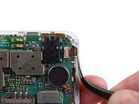
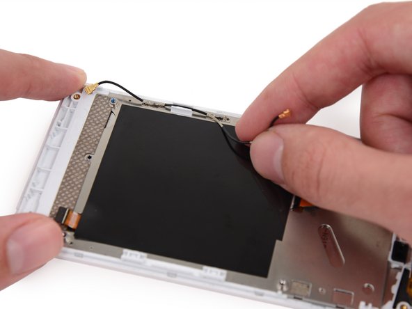
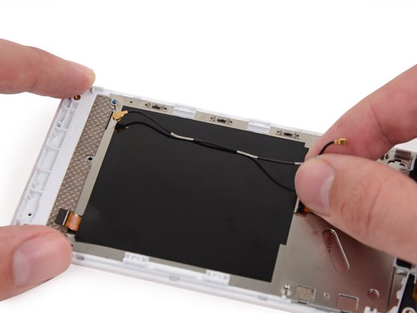
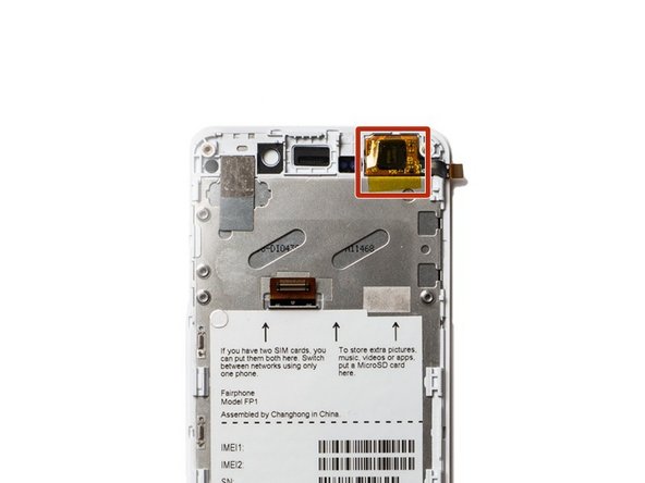
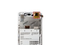
Remove the antenna interconnect cable from the display assembly.
In this step you need to replace the earpiece speaker too, follow this guide: Fairphone 1 Display Assembly Replacement
Don't forget to put two little rubber parts over the proximity sensor and the notification LED on the new display, otherwise the proximity sensor will bug out later. They are visible in the picture for Step 18.
Sadly I lost the small rubber part in front of the proximity/light sensor.
Any idea where i can get it, because I have now the bug, everytime a call comes in, the display will turn and stay black until the call is ended :-(
Thanks!
pappou -
Which parts are the proximity sensor and the notification LED?
Indeed, the rubber parts didn't came at first, and lastly also the speaker was stuck on the old phone, so this was a rather unwelcome discovery for a non-technician wanting to repair the phone. By lifting it off a small rubber joint came with it so this had to be removed before gluing it back on the new front (a protective adhesive tape needed first to be removed too so this speaker could nicely be glued on. (of course all this is written still without reassembling my phone). Erik
It worked ! I managed to get everything back in place, even after suddenly finding another small rubber thing on my table which after magnifying the pictures here, seemed to have fallen of the motherboard.
So, a part from the fact that this Dragontrail glass is not so strong as promised, I'm really happy I could repair my Fairphone myself.
-
-
-
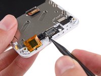
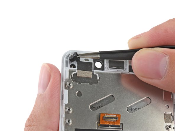
Remove the rubber guide to the right of the earpiece speaker recess.
-
Your replacement display will have a piece of yellow tape covering the touch sensor chip. Do not remove this tape; if you do, your phone may not work after reassembly.
When putting the rubber placeholder back in place watch for the right direction. It has a bigger and a smaller hole and they must be placed in the right orientation, otherwise the proximity sensor does not work properly (display is turned off immediately when calling someone)
-


To reassemble your device, follow these instructions in reverse order.
To reassemble your device, follow these instructions in reverse order.
İptal et: Bu kılavuzu tamamlamadım.
102 farklı kişi bu kılavuzu tamamladı.

16 Yorum
The Camera is not mentioned at all. It's glued to the Display and yet still working, it can't focus anymore. So I might have to get a new one as well.
Awesome! Did it, and everything still works. Mighty pleased with myself. Thank you, iFixit!!!
Just did it successfully. Great guide!
ouf, j'ai réussi à remplacer mon écran fissuré suite à une chute. Je suis prêt à contribuer en traduisant les parties complexes du tutoriel en français, si quelqu'un peut m'indiquer la marche à suivre pour proposer une version FR.
Plusieurs étapes sont assez complexes - stressantes (comme indiqué l'APN qui reste collé et ne se détache pas de la carte mère par ex.) mais ne requièrent aucune compétence spécifique, juste du doigté et de la patience.
En tout cas merci
salut, toi aussi tu dirais que ca prend environ une heure ?
cazeph -
Pfew!!! Done... Thanks for all the pics, comments, and instructions (Nico/France)
It works perfectly and looks like a new phone! Wow!
I also avoided step 21 and removed the wifi cable together with the board.
Hint for camera step 18: It was glued on very well. What I did was to lift the mainboard slighty and entered with a screwdriver between camera and case. Finally I saw that the metal plate came off too which you already have in your new case. But it was then much easier to remove it after the disassembly with my fingernails. To be able to do this step you have to remove the power button but I would recommend that anyway.
Great pictures and explanations!! Thank you very much! It took me about 30 minutes to do it.Happy! :-)
45 min. But camera lost autofocus :-(.
It was glued too hard so removal was difficult and probalbly damaged it…
45 min. But camera lost autofocus :-(.
It was glued too hard so removal was difficult and probalbly damaged it…