Giriş
This repair guide was authored by the iFixit staff and hasn’t been endorsed by Google. Learn more about our repair guides here.
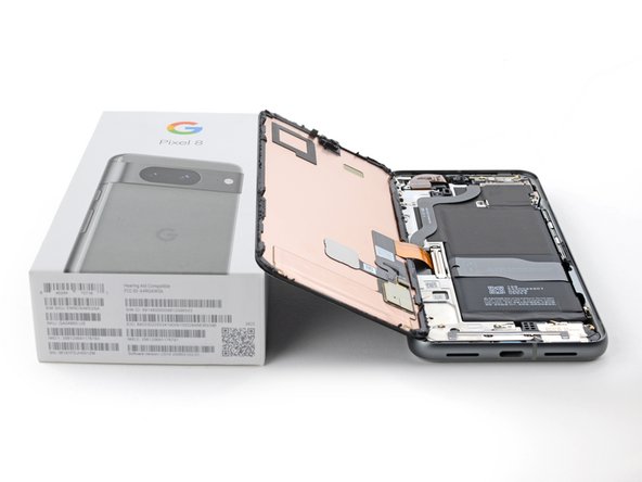
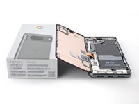
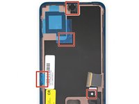
Use this guide to replace the earpiece speaker in your Google Pixel 8.
If phone call sound is muffled or there's no sound at all, it might be time to replace the earpiece speaker.
The earpiece speaker is tucked under the logic board and requires a lengthy disassembly of removing both the logic board and the battery to access the speaker.
You'll need replacement adhesive to complete this repair.
Note: This guide was made with the 5G mmWave antenna model of the Pixel 8. If you have the non-mmWave version, you can still use this guide—just skip the steps that mention the 5G mmWave antenna.
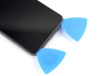
Neye ihtiyacın var
-
-
Unplug all cables from your phone.
-
Completely power off your phone.
-
-
-
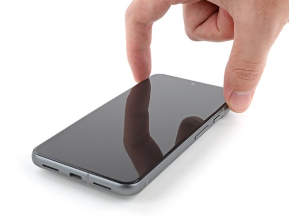
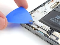
Firmly press a SIM eject tool, bit, or straightened paper clip into the SIM card tray hole on the left edge of your phone until the tray ejects.
-
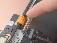
Remove the SIM card tray.
-
-
-
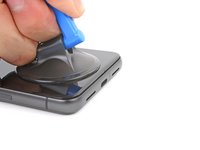
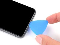
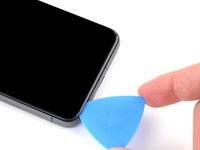
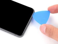
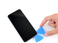
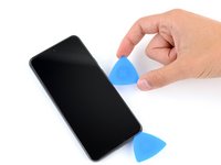
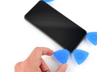
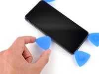
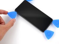
Measure 3 mm from the tip and mark the opening pick with a permanent marker.
-
-
-
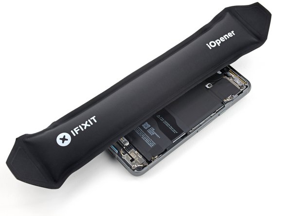
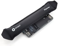
Heat an iOpener and lay it on the bottom edge of the screen for two minutes to soften the adhesive.
-
-
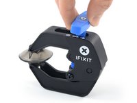
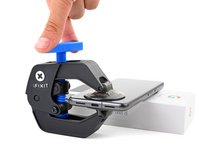
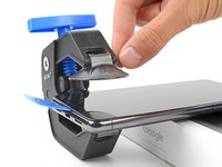
Bu adımda kullanılan alet:Clampy - Anti-Clamp$24.95
-
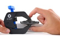
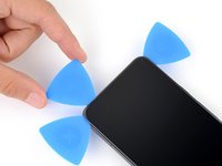
Pull the blue handle backwards to unlock the Anti-Clamp's arms.
-
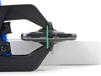
Place your phone screen side up on an object so it will rest level between the Anti-Clamp's arms—the bottom edge should be hanging off.
-
Slide the arms over the left edge of your phone, so you have access to the bottom edge.
-
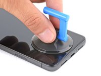
Position the suction cups as close to the center of the bottom edge as possible.
-
Squeeze the cups together to create suction.
-
-
-
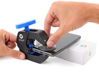
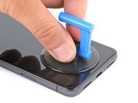
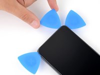
Pull the handle forward to lock the arms.
-
Turn the handle clockwise one full turn (360 degrees), or until the suction cups begin to stretch.
-
As the cups stretch, make sure they stay aligned with each other. If they keep slipping, remove the Anti-Clamp and apply tape for the cups to stick to.
-
-
-
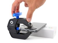
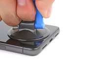
Wait one minute for a gap to form between the screen and frame.
-
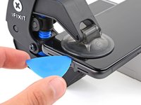
Insert an opening pick into the gap.
-
Pull the blue handle backwards to unlock the arms and remove the Anti-Clamp using the pull tabs on the suction cups.
-
Skip the next two steps
-
-
-
Apply a suction handle to the center of the screen's bottom edge.
-
-
-
Pull up on the suction handle with strong, steady force until a gap forms between the screen and frame.
-
Insert an opening pick into the gap.
-
-
-
The screen cable is a little less than halfway up the left edge of the phone. Be very careful here to avoid tearing the cable.
-
There are many spring contacts around the perimeter of the phone. Be very careful in these areas to avoid bending the contacts.
-
-
-
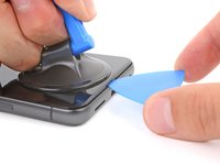
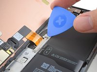
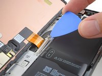
Slide the opening pick along the bottom edge to separate the adhesive securing it.
-
Leave the pick in the bottom right corner to prevent the adhesive from resealing.
-
-
-
Apply a heated iOpener to the right edge of the screen for two minutes.
-
-
-
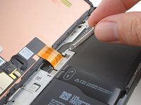
Insert a second opening pick under the bottom right corner of the screen.
-
Slide the new pick to the top right corner to separate the adhesive securing the screen's right edge.
-
Leave the pick in the top right corner to prevent the adhesive from resealing.
-
-
-
Insert a third opening pick under the bottom edge of the screen.
-
Slide the new pick to the bottom left corner.
-
Leave the pick in the bottom left corner to prevent the adhesive from resealing.
-
-
-
Apply a heated iOpener to the left edge of the screen for two minutes.
-
-
-
Insert a fourth opening pick under the bottom left corner of the screen.
-
Slide the new pick to the top left corner to separate the adhesive securing the screen's left edge.
-
Leave the pick in the top left corner to prevent the adhesive from resealing.
-
-
-
Apply a heated iOpener to the top edge of the screen for two minutes.
-
-
-
Insert a fifth opening pick under the top edge of the screen, near the left corner.
-
Slide the opening pick to the top right corner to separate the adhesive securing the screen's top edge.
-
-
-
Place a small box or stack of books to the left of your phone so you can prop up the screen while disconnecting its cable.
-
Swing up the right edge of the screen like the front cover of a book.
-
Prop up the screen so you can access the screen cable.
-
-
-
Use an opening pick to pry up the upper edge of the screen cable cover.
-
Remove the cover.
-
-
-
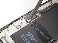
Insert the point of a spudger under the top left corner of the screen's press connector.
-
Gently pry up and disconnect the cable.
-
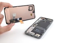
Remove the screen.
-
-
-
When handling your screen, grip it by its edges.
-
When placing the screen on your work area, make sure nothing is touching the bottom of the screen. Consider placing it on a soft, lint-free cloth.
-
-
-
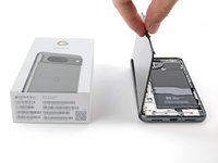
Use the pull tabs to remove the liners covering the front camera cutout, the rear camera pad, the back of the screen, and the perimeter adhesive.
-
Reconnect the screen cable and reinstall its cover.
-
This is a good point to test your phone before sealing it up. Temporarily power on your phone and make sure it works as expected. Power it down before continuing.
-
Firmly press the screen into place on the frame. You should feel the clips "pop" into place.
-
Press firmly around the perimeter of the screen to secure it with the new adhesive.
-
Follow this guide to calibrate the fingerprint sensor.
-
-
-
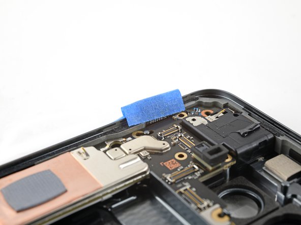
Bu adımda kullanılan alet:Tweezers$4.99
-
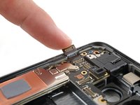
Slide the tip of an opening pick under the plastic shim until you can grip it with tweezers or your fingers.
-
-
Bu adımda kullanılan alet:FixMat$36.95
-
Use a T3 Torx driver to remove the two 5 mm‑long 3IP Torx Plus screws securing the USB‑C port bracket.
-
-
-
Use tweezers, or your fingers, to remove the USB-C port bracket.
-
-
-
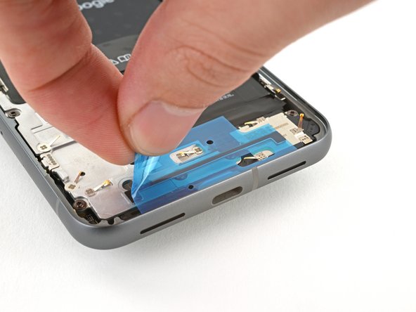
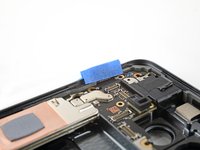
Remove the clear liner from the shim.
-
Use the markings on the midframe to align the left side of the shim and press it into place.
-
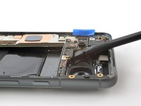
Use the flat end of a spudger to firmly press down along the whole shim to secure it.
-
Remove the blue liner.
-
-
-
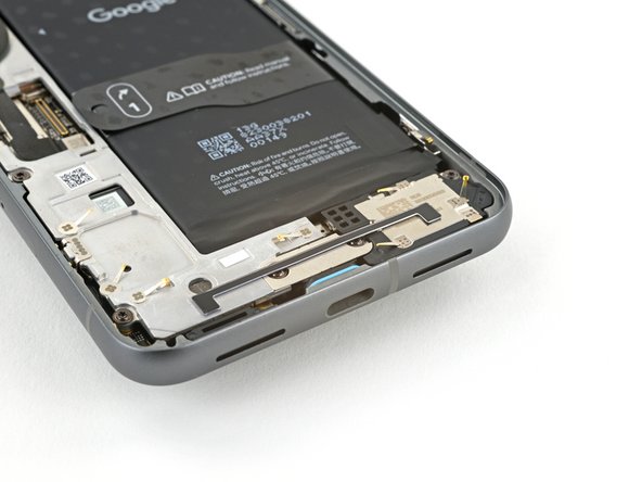
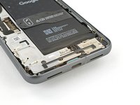
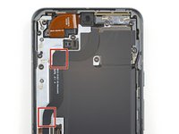
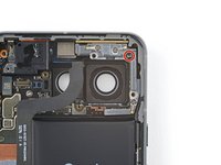
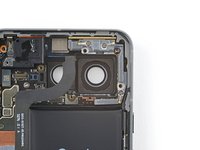
Use a T3 Torx driver to remove the 5 mm‑long screw securing the bottom speaker.
-
-
-
Insert the point of a spudger between the top right corner of the bottom speaker and the frame.
-
Pry the bottom speaker up with the spudger to dislodge it from its recess.
-
Remove the bottom speaker.
-
-
-
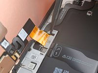
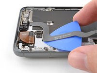
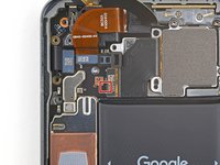
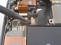
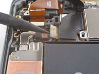
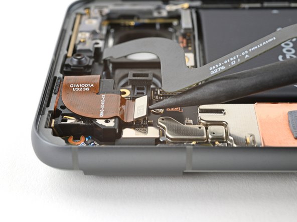
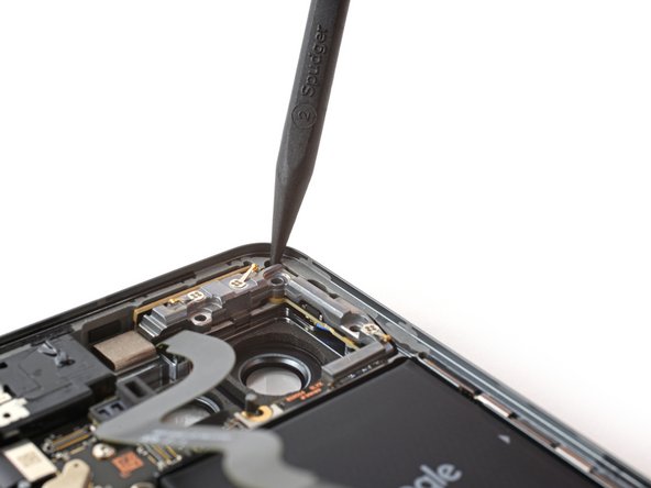
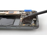
Use the point of the spudger to pry up and disconnect the 5G mmWave antenna cable from the logic board.
-
-
-
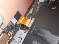
The 5G mmWave antenna cable is secured to the midframe with adhesive in two places.
-
Heat an iOpener and lay it on the left edge of the phone for two minutes to soften the cable adhesive.
-
-
-
Insert an opening pick under the 5G mmWave antenna cable's bottom section of adhesive.
-
Slide the pick toward the top edge of the phone to separate the adhesive.
-
-
-
Move the 5G mmWave antenna cable over the top of the phone to keep it out of the way.
-
-
-
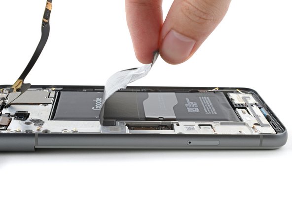
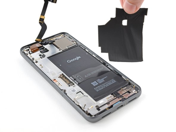
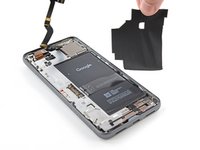
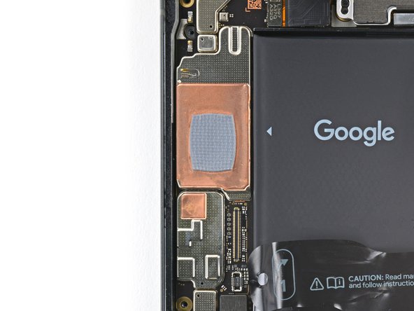
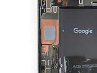
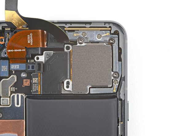
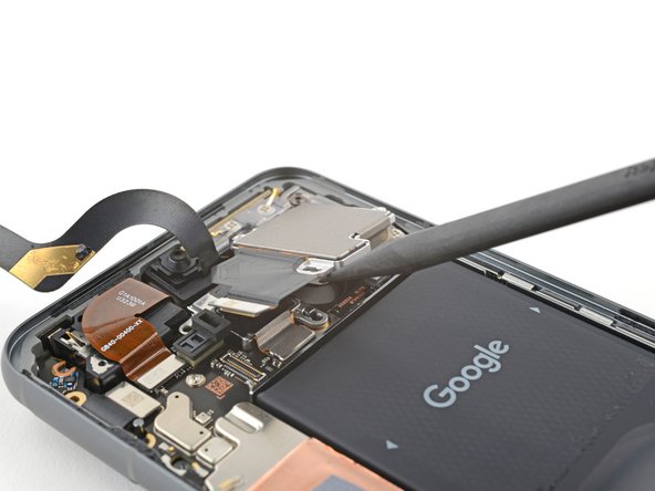
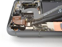
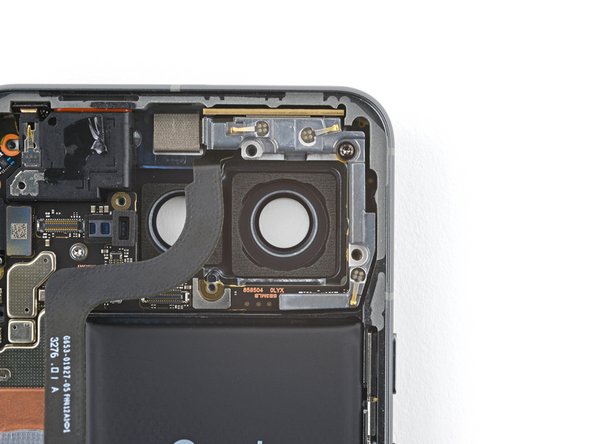
Insert the point of a spudger under the top right corner of the graphite sheet and lift until you can grip the sheet with your fingers.
-
Peel up and remove the entire graphite sheet.
-
-
-
Use a T3 Torx screwdriver to remove the eight 5.1 mm‑long 3IP Torx Plus screws securing the midframe.
-
-
-
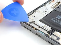
Slide the flat end of a spudger under the bottom right corner of the midframe to separate it from the thermal pad.
-
-
-
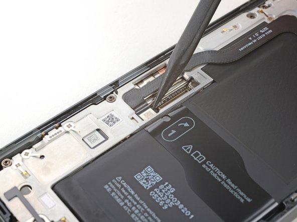
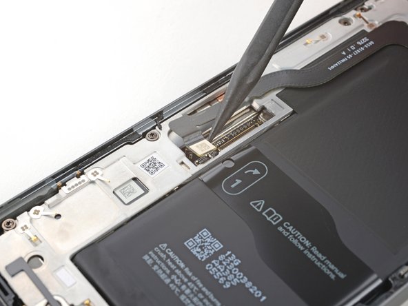
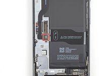
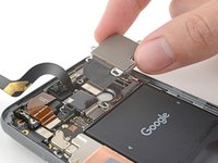
Use a spudger to pry up and disconnect the battery connector.
-
-
-
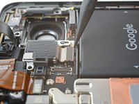
Insert the point of a spudger under the bottom half of the wide rear camera press connector, between the surface-mounted components.
-
Pry up to disconnect the wide rear camera.
-
-
-
Use a T3 Torx screwdriver to remove the two 5.1 mm‑long 3IP Torx Plus screws securing the wide rear camera.
-
-
-
Insert the tip of a spudger under one of the wide rear camera screw hole cutouts.
-
Use the spudger to lift the camera out of its recess.
-
Remove the camera.
-
-
-
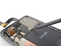
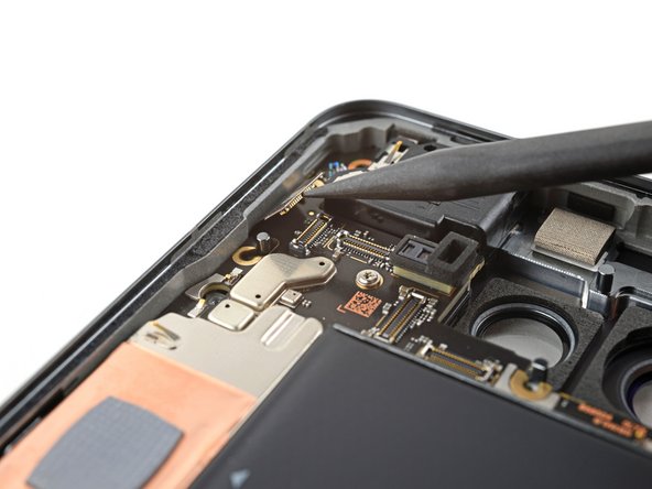
Use a spudger to pry up and disconnect the ultrawide rear camera press connector from the logic board.
-
-
-
Insert the tip of a spudger under the top screw cutout on the ultrawide rear camera.
-
Use the spudger to lift the camera out of its recess.
-
Remove the camera.
-
-
-
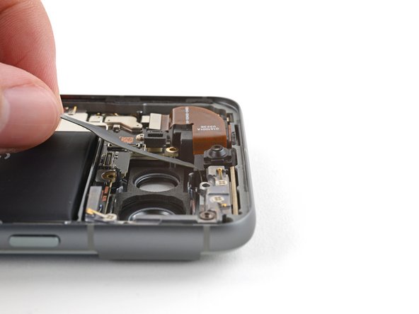
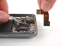
Use a spudger to pry up and disconnect the front camera press connector from the logic board.
-
-
Bu adımda kullanılan alet:Tesa 61395 Tape$5.99
-
Slide an opening pick under the front camera cable to separate the adhesive.
-
-
-
Move the antenna cable toward the right edge of the phone to free the front camera.
-
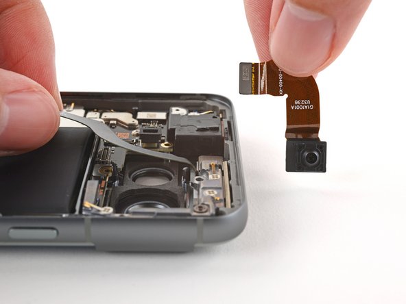
Remove the front camera.
-
-
-
Use a T3 Torx screwdriver to remove the 5.1 mm‑long 3IP Torx Plus screw securing the 5G mmWave antenna bracket.
-
-
-
Insert the point of a spudger in the notch at the top right corner of the 5G mmWave antenna bracket.
-
Pry up with the spudger to separate the bracket from its recess in the frame.
-
Remove the bracket.
-
-
-
Pull the antenna and its cable out of the frame and remove it.
-
If your cable disconnects from the antenna, don't worry! Align the cable press connector over its socket and press down with your fingers until it snaps into place.
-
-
-
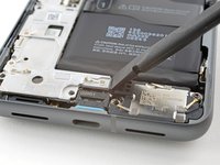
Use a spudger to pry up and disconnect the interconnect cable press connector.
-
-
-
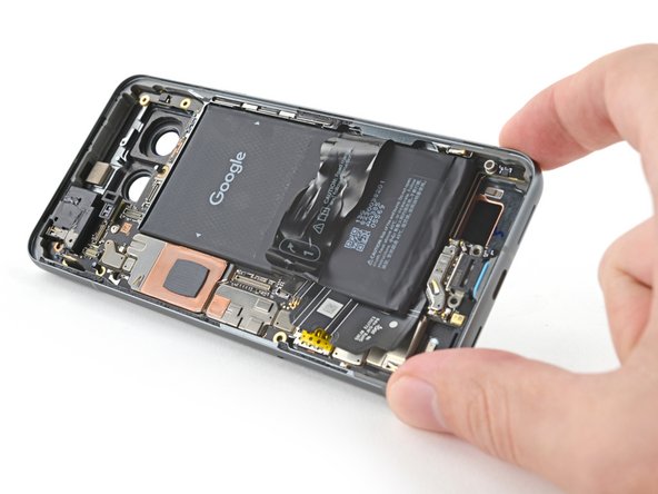
Flip your phone back over and lay it on your workspace.
-
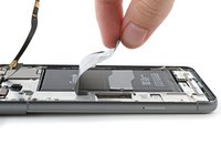
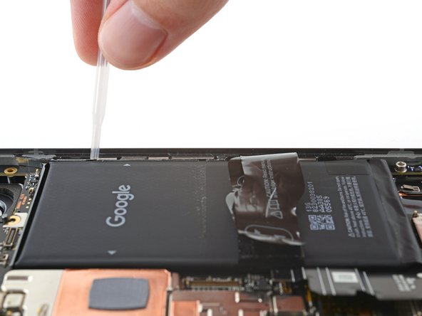
Apply a few drops of highly-concentrated isopropyl alcohol (>90%) along the right edge of the battery.
-
-
-
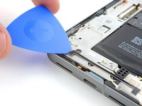
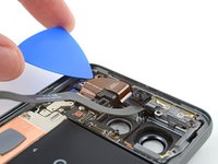
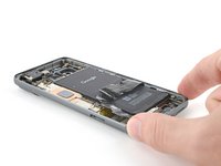
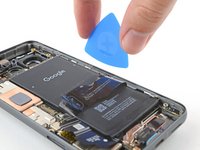
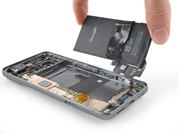
Insert the flat side of an opening pick between the right edge of the battery and frame.
-
-
-
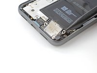
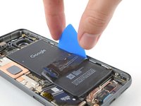
Firmly secure your phone with one hand.
-
With your free hand, pry the battery up with the pick. Maintain constant pressure on the pick until the battery separates from the frame.
-
-
-
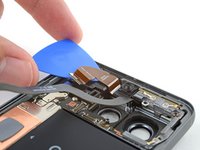
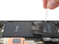
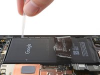
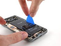
Use the opening pick to lift the battery and separate the remaining adhesive.
-
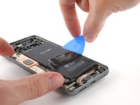
Remove the battery.
-
-
-
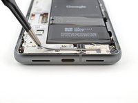
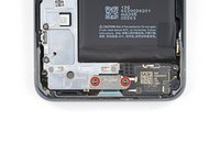
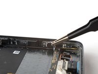
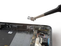
Use a T3 Torx screwdriver to remove the 2.5 mm‑long 3IP Torx Plus screw securing the grounding bracket to the bottom right edge of your phone.
-
-
-
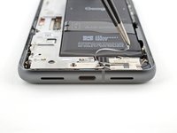
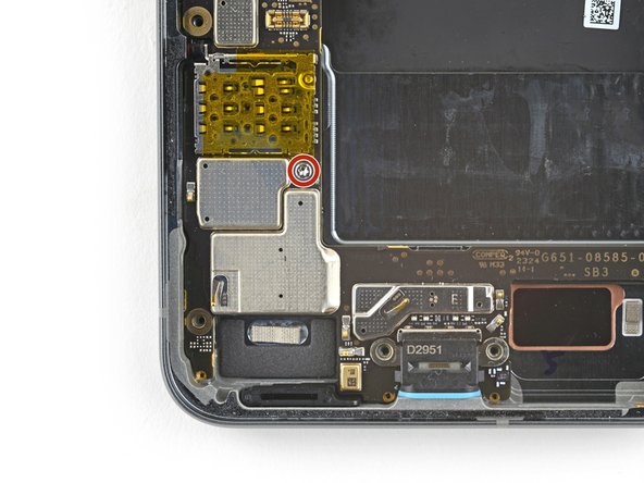
Use a T3 Torx screwdriver to remove the two 3.5 mm‑long 3IP Torx Plus screws securing the logic board.
-
-
-
Move the interconnect cable away from the frame to keep it from snagging on the logic board.
-
Optionally, you can tape the cable to the left edge of the phone.
-
-
-
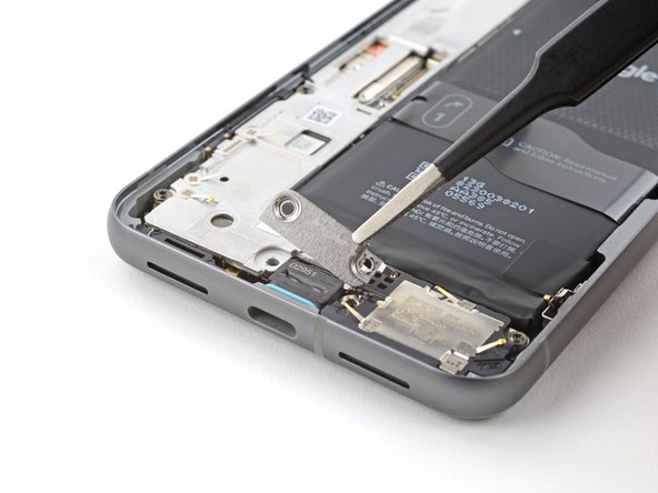
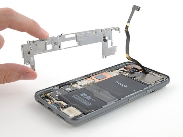
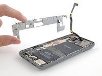
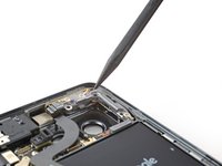
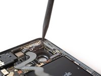
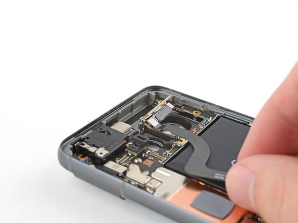
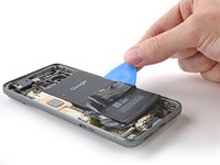
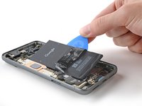
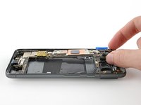
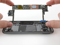
Use the flat end of a spudger to lift the top edge of the logic board until you can grip it with your fingers.
-
-
-
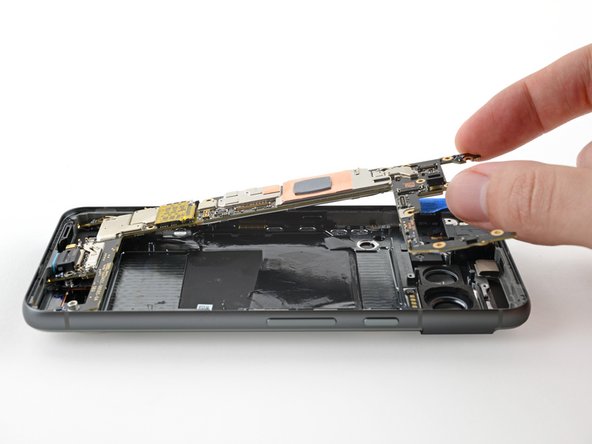
Lift the top of the logic board upward to release its bottom clip.
-
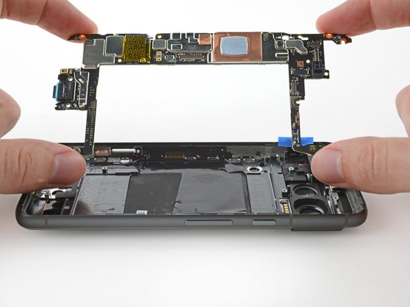
Remove the logic board.
-
-
-
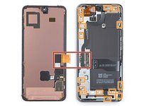
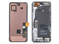
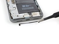
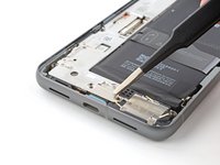
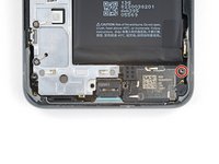
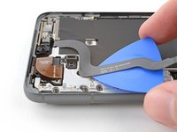
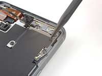
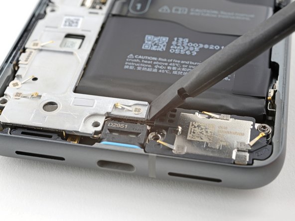
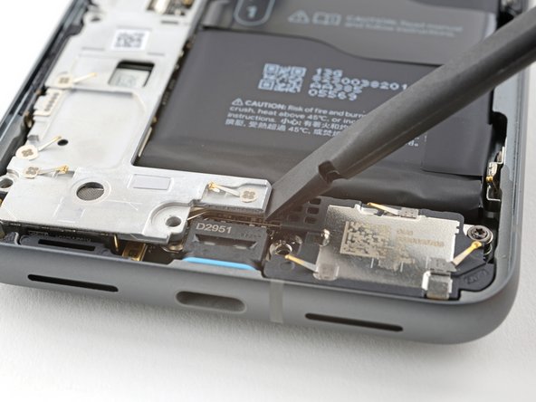
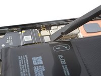
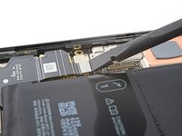
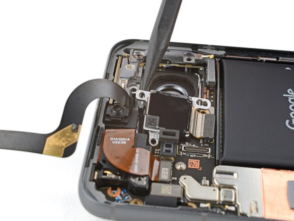
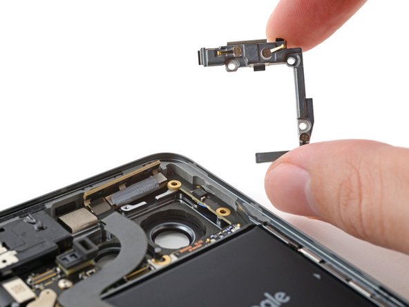
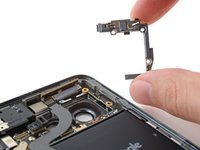
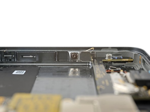
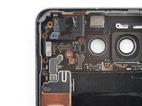
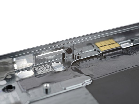
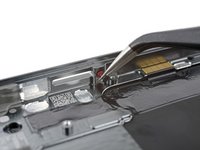
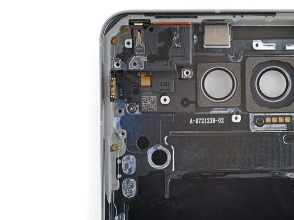
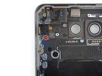
Use a T3 Torx driver to remove the 2.5 mm‑long 3IP Torx Plus screw securing the earpiece speaker.
-
-
-
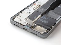
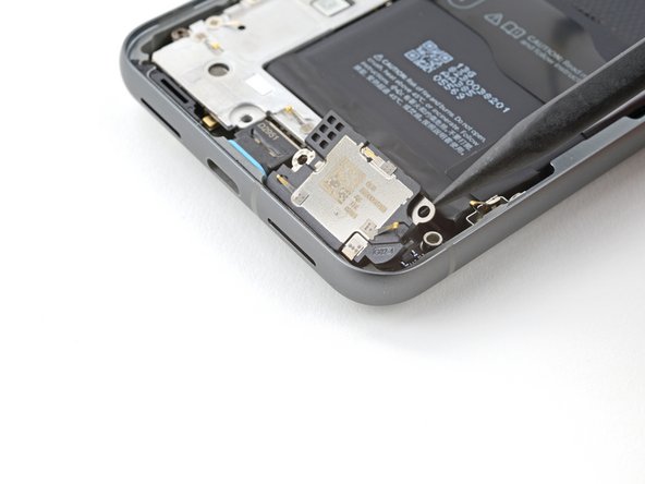
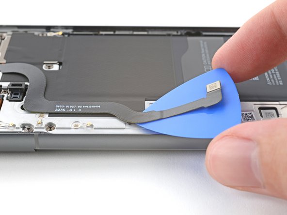
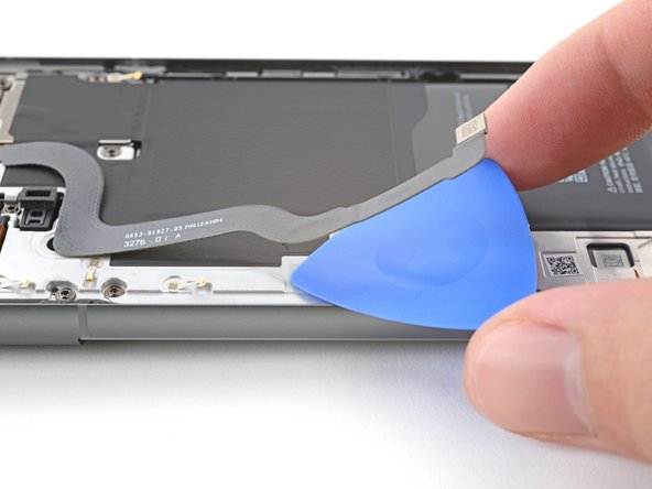
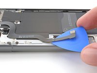
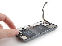
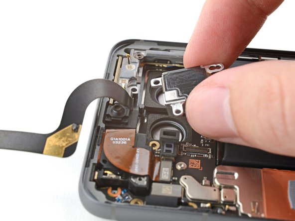
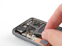
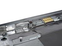
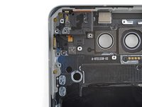
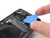
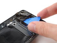
Slide an opening pick under the bottom right corner of the earpiece speaker to separate it from the frame.
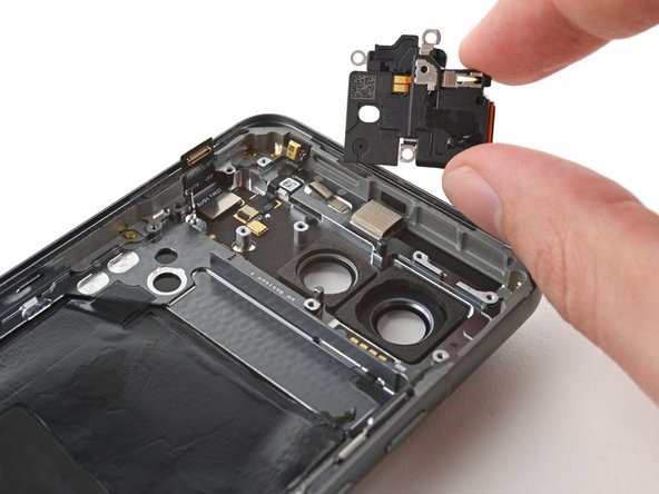
-
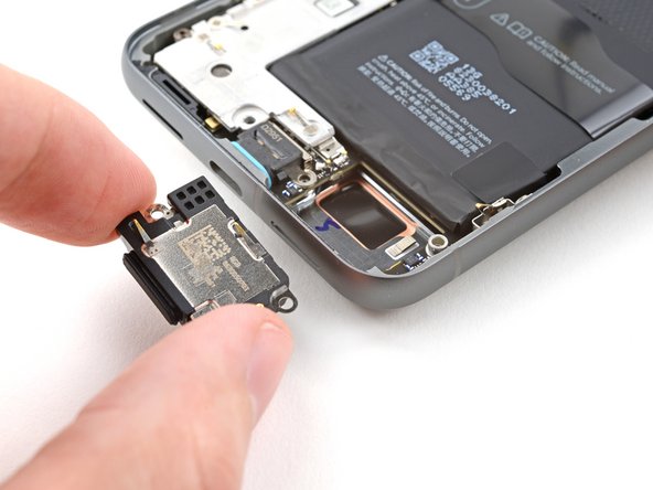
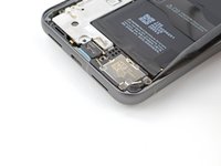
Remove the earpiece speaker.
-


To reassemble your device, follow these instructions in reverse order.
To run a diagnostics test with the built-in Pixel Diagnostic tool, click here.
Take your e-waste to an R2 or e-Stewards certified recycler.
Repair didn’t go as planned? Try some basic troubleshooting, or ask our Google Pixel 8 Answers Community for help.

