Giriş
This guide will walk you through the process of replacing the motherboard in the HP All-In-One PC Model 24. Whether you're upgrading or performing maintenance, this step-by-step tutorial will help you safely disassemble, replace, and reassemble your system with ease.
Neye ihtiyacın var
-
-
Pry Open the Front Panel: Using the prying tool, gently slide it between the front panel and the main body of the PC at the bottom of the computer. Work your way around the bottom edge, carefully detaching the clips holding the panel.
-
Remove the Front Panel: Lift the front panel away from the PC once all clips are detached. Set it aside in a safe place.
-
-
-
Turn the PC Around: Place the PC screen-side down on a soft surface to avoid scratching the screen.
-
Pry Open the Bottom Panel: Gently pry open the bottom panel using the prying tool. Work your way around the panel to detach it from the frame.
-
-
-
Unscrew the Front Panel Screws: Use a screwdriver to carefully remove the screws securing the front panel. Keep these screws in a safe place.
-
-
-
Locate the Stand Screws: Turn the PC over so that the back is facing up.
-
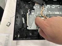
Unscrew the Stand: Use the screwdriver to remove the screws securing the stand.
-
Remove the Stand: Once the screws are removed, carefully detached the stand from the PC (should be able to pull up and out).
-
-
-
Release the Clips: Using a plastic prying tool, gently slide it between the screen and the frame. Work your way around the edges, carefully releasing the clips.
-
Power Button Board: Make sure not to damage this part.
-
Life the Screen: Once all the clips have been undone, gently lift the screen away from the frame.
-
-
-
Disconnect the Ribbon Cable: Gently lift the small locking mechanism or tab that secures the ribbon cable.
-
Carefully remove the Ribbon Cable: Once the tab is lifted, gently pull the ribbon cable out of its connector.
-
-
-
-
Disconnect the Cables: Disconnect each display cable from its connector on the motherboard. Do this by pulling on the cables very close to the connector perpendicularly to the board. Pulling directly up prevents any damage to the plug.
-
-
-
Locate the Storage Drive
-
Unscrew the Storage: Use a screwdriver to remove any screws securing the storage drive.
-
Very Small Screw: This screw requires the precision screwdriver.
-
Remove the Storage Drive: Once the screws are removed, remove the drive from the compartment. Do this by pulling directly away from the connector.
-
-
-
Identify the Battery Holder: Look for the small clip or latch that holds the battery in place. This may be a metal latch.
-
Release the Battery: Using the prying tool or your fingers, gently press the clip that secures the battery.
-
Remove the Battery: Once the clip is released, lift the battery out of its holder.
-
-
-
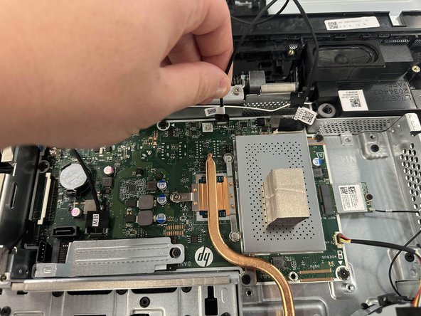
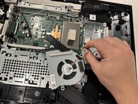
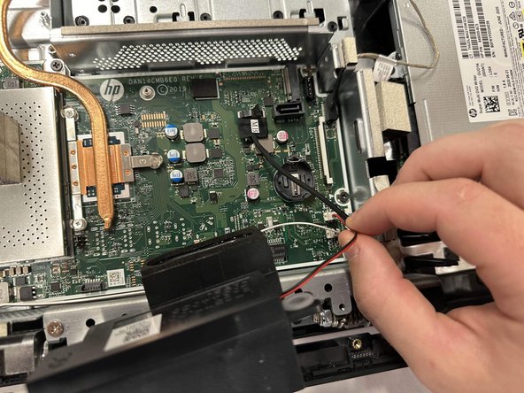
Disconnect the Fan's Power Cable: Locate the fan's power cable connected to the motherboard. Gently unplug the cable by pulling on the wire very close to the connector perpendicular to the board.
-
Unscrew the Fan: Use a screwdriver to remove the screws that secure the cooling fan in place. There are only three screws.
-
Remove the Fan: Lift the cooling fan away from the CPU and motherboard.
-
Cooling bar system: Do not remove this, yet.
-
-
-
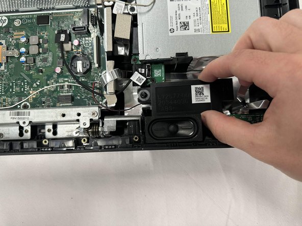
Locate the Speakers: There should be the left and right speakers.
-
Disconnect the Speaker Cables: Gently disconnect the cables by pulling the wires directly above the plugs perpendicular to the board.
-
Remove the Speakers: Carefully lift the speakers out of their compartments. To lift them they have to be pushed down and out of the locking studs. Be careful not to lose the rubber gaskets that go around the locking studs.
-
-
-
Disconnect the Cable: Gently unplug the camera's cable from its connector on the motherboard by pulling on the wire perpendicular to the board.
-
-
-
Release the Cable's Connector: Carefully release the ribbon cable from its connector on the motherboard. The connector has a latch, gently lift it up to release the cable. The same way as in step 6.
-
Disconnect the Ribbon Cable: Once the latch is released, gently pull the ribbon cable out its connector.
-
-
-
Unscrew the Power Button: Use a screwdriver to remove the screws holding the button in place. Keep the screws in a safe location for reassembly.
-
Gently Detach the Power Button: Once the screws are removed, carefully detach the power button from its mounting position. Make sure to remove the ribbon cable carefully so it is not damaged.
-
-
-
Locate the WiFi card
-
Unscrew the WiFi card: The WiFi card is secured with one screw. Use the precision screwdriver to remove the screw holding the WiFi card in place. Keep the screw in a safe location.
-
Remove the WiFi Card: Once the screw is removed, gently pull the WiFi card directly away from the PCIs slot. Be careful not to apply excessive force, as the card can be fragile.
-
-
-
Disconnect the Disc Drive: Gently unplug the cable. Take care to pull on the ribbon above the connector, not the wire or the connector, to avoid damaging the cable.
-
-
-
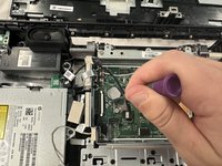
Unscrew the Motherboard: Use a screwdriver to remove the screws around the edges of the motherboard.
-
Unscrew the Cooling Bar: Loosen the screw. This screw should not come out.
-
Removing the Motherboard: Lift the motherboard and cooling rod together out of the PC.
-


To put in the new motherboard follow the same steps in reverse with the new motherboard.
İptal et: Bu kılavuzu tamamlamadım.
2 farklı kişi bu kılavuzu tamamladı.