Giriş
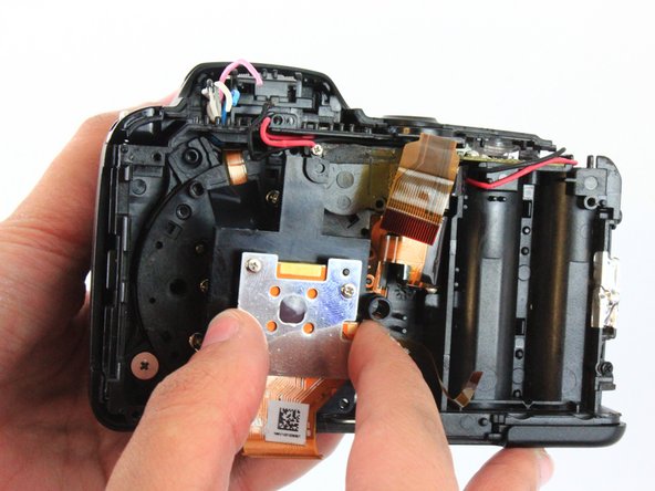
The guide will assist in opening the camera, desoldering motherboard connections and replacing the image sensor.
Neye ihtiyacın var
-
-
There are six screws attaching the back housing to the camera. Remove the screws from the body with a PH000 screw head.
-
Two 1.5x2.5mm screws on the right side.
-
Two 1.5x2.5mm screws on the underside.
-
Two 1.5x2.5mm screw on the left side.
-
-
-
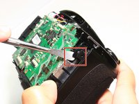
After removing the screws, use a metal spudger or plastic opening tool to push the back cover out.
-
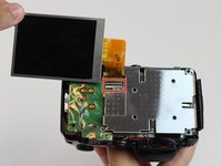
Remove the back housing of the camera by lifting it directly up.
Note:
There are 3 locking cam-lugs along the top edge of the back plate. These slot over the top of matching very delicate moulded catches. Carefully lift and lever this top edge first.
-
-
-
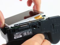
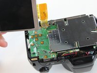
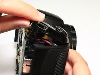
Insert the tips of your fingers into the space between the screen and back-plate.
-
Gently lift the screen up and out of the frame.
-
-
-
-
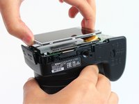
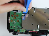
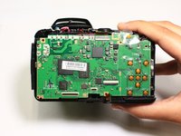
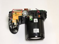
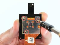
Remove the screws from the silver back-plate with a PH000 screw head.
-
Two 1.5x2.5mm screws on the left side.
-
One 1.5x2.5mm screw on the right side.
-
-
-
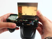
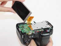
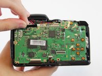
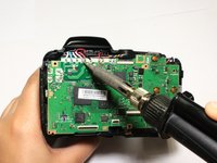
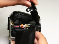
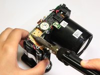
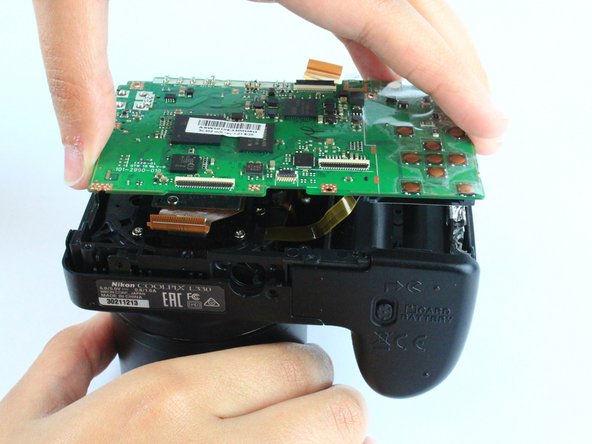
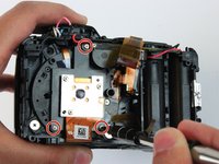
Remove the screws holding the motherboard with a PH000 screw head.
-
Two 1.5x2.5mm screws on the right side.
Err, I don’t think that marked capacitor will hold much charge, though that’s not to say you can’t discharge the flash capacitor as described. The flash capacitor itself will be a large cylindrical component, probably somewhere close by underneath, on the other end of two of those soldered wires.
-


To reassemble your device, follow these instructions in reverse order.
To reassemble your device, follow these instructions in reverse order.
Ekip

USF Tampa, Team 2-10, Cagle Spring 2016 USF Tampa, Team 2-10, Cagle Spring 2016 üyesi
USFT-CAGLE-S16S2G10
4 Üyeler
14 adet Kılavuz yazıldı