Giriş
Desoldering technique with [gootwitck mesh], hot air station and yihua soldering iron. (hot air at 100 ° C helps to preheat the control logicboard.)
Neye ihtiyacın var
Videoya Genel Bakış
-
-
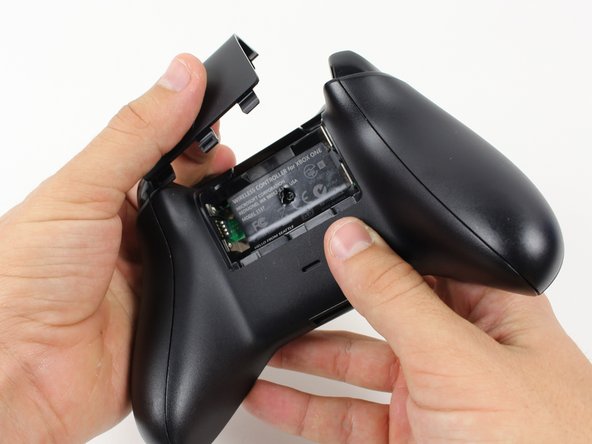
Grip the controller firmly to remove the side handles, wedging a spudger into the seam between the front and handle plates.
-
Pry the side plate away from the front plate by moving the spudger back and forth. You will need to do this all the way around the side plate's seam.
One you take it off, is it possible to click it back in?
As long as you don’t exceed the couple tons you need to take it off you should be able to put it back.
Brandon -
I don’t have a squdger
getting those handles back on seems impossible, they just dont fit as well, a gap remains even after snapping into place.
Dont think ill be doing this in the future
edit: wiggled the bo9ttom middlewith the handles off and somethign finally “clicked” into place for that extra 1/4 mm for the down arrow on my D-Pad to click back up into place!.
-
-
-
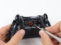
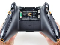
Use a screwdriver and punch a hole directly in the center of the label.
-
Remove the five 10mm screws located on the back of the controller using the TR8 Security Torx Screwdriver.
It's a t8 or t9 security bit btw, I got the top two out with a regular T8, but the bottom two and middle needed a T9 Security bit.
All five faceplate/backplate screws in the controller I disassembled were T8 security fasteners.
The T8 is only good for the middle screw on my One S controller. The others require something bigger
These requires SECURITY Torx bits (they have a cannulated hole in the driver). I don't believe the iFixIt branded driver is cannulated but you can buy a set of bits from DeWalt DWAX200 which is overkill but has what you need.
The driver that iFixIt sells is cannulated.
where do you get this dumb ass screw driver
You can bypass it with a 1.5mm flathead.
thank you for this. worked for me
TR9. A $10 kit from Walmart has the bit/driver in it and extra goodies to make life simple.
As weird as it sounds, the top 2 came out for me with a flathead- but the bottom two and the middle one wont
-
-
-
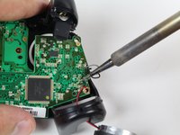
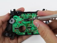
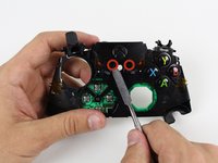
De-solder the soldered joints while holding the red and black wires down on the top motherboard.
-
De-solder the black and gray wires that are attached to the top motherboard.
-
Remove the rumble motors and set them aside.
Steps 6-8 aren't completely necessary, and are very risky if you aren't good at soldering. It would seem the only reason to remove the motherboard and mess with all this soldering is just so you can reach both screws on the trigger in step 10. However, you can reach them already with a small-bodied screwdriver. Although you might have to rest the screwdriver on the black square processor to reach the bottom screw, it shouldn't damage the processor or motherboard to jimmy that screw out.
Thank you very much. There's no need for soldering.
anguo -
like mentioned by ‘Robert Rapier’ you can skip the de-soldering in most cases,
for example cleaning or changing the buttons is doable, but the grey and black wires are pretty short
and wired through the inner case so it can get a bit fiddly and you have to be careful not to damage them in the process.
If you have a soldering station around i would still recommend using it.
-
-
-
-
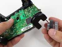
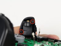
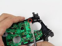
Unscrew the two 7mm T6 screws located near the rumble motor sockets.
Are these just T6 screws or Torx security T6 that is cannulated?
The outer screws are security screws. The ones on the system boards are Torx.
Rongwey -
-
-
-
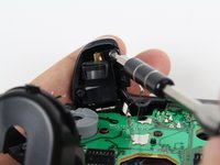
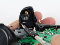
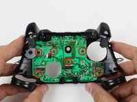
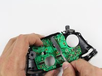
Firmly grip sides of motherboard near the middle.
-
Lift upwards while slightly wiggling the motherboard forward and backward.
-
-
-
Remove the yellow tape holding the wires in place on the front of the controller.
-
-
-
Remove the six T6 Torx screws located on the bottom motherboard.
Where can I find the connectors at for the motherboard??
This guide completely skips the part about removing the trigger buttons. There are 2 screws per trigger that need to be removed so there are actually 10 T6 screws to remove.
There’s also 2 small rumble packs under the trigger buttons that no one mentioned. Someone got lazy when writing this step.
I didn't need to remove them. Leave the triggers on and saved some effort
Hey @jasonasnes good catch! It looks like maybe they forgot to add the trigger/trigger rumble motor prerequisite, so I went ahead and added that in there. That guide makes no mention of how the rumble motors are attached, but I think they’re soldered to the motherboard, so I added a note to desolder those wires prior to removal. I think you could probably also just desolder those wires and leave the triggers in place when removing the motherboard, but I’m not certain! Hope that helps!
@sam I was able to complete this with the missing information but thank you for updating it for those to come in the future. Minus these couple of discrepancies and it’s a great guide. Yes, all 4 of the rumble motors are soldered onto the upper motherboard. Step 6 actually highlights this with the exception of mentioning the 2 small rumble motors in the triggers. You bring up a good point, it might be possible to leave the triggers in place during this process. I used this guide as a teardown instead of as a replacement so I could refurbish the plastic shell and clean the interior of my day one controller so I completely stripped mine. However, I believe that the triggers could remain in place if your goal is to get to the lower motherboard.
You can lift off the top motherboard without desoldering the black/red wires to the large rumble motors, just be careful because the wires are delicate enough that you can break them off at the solder joint. It’s not a huge deal if you do, because they’re long enough that you can strip the ends and have plenty of room to resolder.
You can even very carefully remove the lower motherboard without desoldering the black/gray wires, and without removing the trigger assemblies, but there’s almost no room to work in there if you choose to go this route, because the wires will leave you only at most an inch of space to get in there under the lower motherboard. Also, leaving the trigger assemblies in place makes it very difficult to get the lower motherboard back into place without pinching or moving the conductive rubber button pad.
It's cumbersome but avoids soldering which I'm not experienced with and worked to replace the button membrane for me
-
-
-
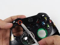
Remove the bumpers by prying them off of the pegs that secure them, using a spudger. They are located on the front and back of the controller.
At some point I had 2 little white pieces come out and I didnt see them till the very end. Does anyone know where these are spossed to go? They kinda look looe shims? Thank you.
They go behind the trigger buttons on the board against the metal. Narrow side towards the button.
Rongwey -
-
-
-
Lift the piece surrounding the Home button off of its pegs.
-
Pry it off of the other side, using a spudger on the pins.
2 things missing in this step:
1) You will have to press down on the power button in order to release the plastic retaining piece.
2) The button that syncs the controller to the system completely separates from the plastic frame. If you're not careful you could lose the thing.
Thanks NavyVet2015!
The sync button fell out on me and I was pondering what it was for a while.
Nothing is holding that little guy in so watch it!
-


To reassemble your device, follow these instructions in reverse order.
To reassemble your device, follow these instructions in reverse order.
İptal et: Bu kılavuzu tamamlamadım.
3 farklı kişi bu kılavuzu tamamladı.

4Kılavuz Yorumları
Do you know where we can get the original analogue module for the joystick?
it does not exists, so you should buy generic replacement spare part
I just created welding related blog and you will find here more: bestmigwelders.org