Giriş
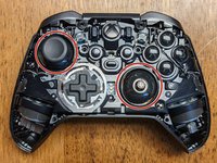
This guide can be used as a prerequisite to repair or replace parts on the Elite Series 2 Controller.
Neye ihtiyacın var
-
-
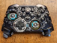
Slightly differing from the previous model, the faceplate needs to be removed before anything else. Begin by removing the joystick caps and d-pad cover.
-
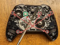
Once these are removed, you'll need to begin working an opening tool along with the picks around the faceplate starting at the top-left or top right.
-
Slowly work around the faceplate to loosen the clips using primarily the plastic opening tools to prevent any damage to the faceplate & internal components.
-
-
-
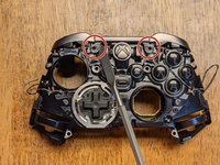
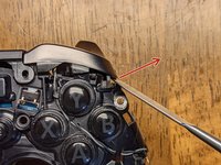
This is the only part in the face removal I would suggest using the metal spudger as you'll need a little more leverage to release the adhesive holding the faceplate down.
-
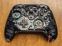
Insert the metal spudger in the area located but only as far as you need to get some leverage to pry the faceplate up. Work cautiously and slowly as this can easily damage components.
-
The adhesive is located in two places and because this doesn't seal the device together for IP-67/68 requirements, it isn't necessary to replace.
-
-
-
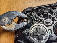
The joysticks are screwed onto the stem of the potentiometers and will need some convincing to remove. These will need to be twisted counter-clockwise to remove with either of the following methods:
-
Method 1: Using a joystick cap - try this first regardless as it has less possibility of damaging the device. Insert one of the joystick caps to each of the joysticks and attempt to twist by hand. If they are too tight, proceed to the second method.
-
Method 2: Using pliers - using as little force as necessary to prevent slipping, squeeze the joystick near the base, where the bevel allows for a "flat edge" that the pliers can grip. Once these are loose, revert to method 1 to continue the removal.
YOU WILL BREAK THE ANALOGS if you force them with pliers! Symptom of them breaking: they start spinning around endlessly, with some resistance and never come undone. Please use a heat gun (300C was enough in all cases of me) to heat up the dome stem and then it comes undone very easily. The problem is some industrial grade loctite on its threads.
Is there anyway of getting them off once you break them ?
Yes, this step is hell. Can't remove sticks correctly, broke one (symptom described above), and second one not working when I put everything back. Why is it so hard to disassemble....
Pliers are a bit too much in my opinion, a bit too easy to strip something essential or gouge the metal, and there is Loctite involved from the factory here also. I'd recommend using the long thumbstick extender locked onto the stick, since it has the rubber grip tip and is longer it should give you enough torque to get the threads unstuck and unscrew the thumbsticks. Use a slight downward force as you turn the stick to make sure the grooves don't strip on either the extender or the stick piece. At least try this first before moving to pliers.
Wish I read the comments first.. I ended up damaging my right stick but was able to move the analog guts back into place and get it functional again. 1/4" socket or box end wrench was a little small, but slight downward pressure gave it grip to screw.
Attempting to just use the analog stick resulted in me shearing the bond between grip and metal and it's all bumpy now.
DON'T USE PLYERS!!!! I now have to buy and solder on 2 new analog potentiometers for my controller this is the second time iFixit's "teardown" has caused me to break some ones stuff luckily this time its mine.
Read the comments and still had to use pliers to get the stick off… screwing in the stick during reassembly seems critical to give it clearance from the plastic face above. To have enough clearance it needs to be super tight again (beyond screwing in by hand) and this is where I broke the tiny screw threads along the stick. It’s clear this was intentionally manufactured to be difficult to repair
I used the tall stick and a towel to maintain grip. Slow form pressure and the sticks loosened pretty easily with zero damage.
I had much success with the heat application method and tall thumbstick. I just used a cheap harbor freight heat gun set to low and held about 8 inches away so I didn't risk melting plastic. After about 20 to 30 seconds of applying heat it was much easier to break them loose.
USE the HEAT on the TIP. 200'C is enaugh for about 30 seconds. There is no need to heat up the comb. The threat and the threadlock are tight tight tight. GL
-
-
-
-
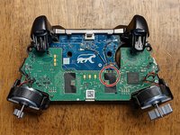
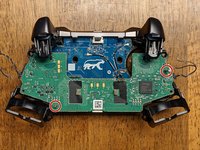
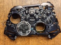
Remove the six T-8 Security screws holding the front and the back of the controller together. Note: one (highlighted green) is covered by a white paste/sticker that crumbles when removed; this lets you know if someone has previously disassembled your device.
-
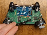
Once the screws are removed, you can insert a spudger under a vibration motor to provide a little leverage to separate the front from the back of the device.
-
The third image shows the front assembly removed from the back cover.
-
-
Bu adımda kullanılan alet:Tweezers$4.99
-
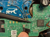
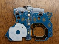
Begin by peeling back the tape (tweezers might help) covering the connection on the green board.
-
While holding the tape back, insert the plastic pointed spudger under the connections, and the force of pushing the spudger under them should be enough to release them from the board.
I’m having trouble reconnecting these cables back to the motherboard.
Hold the cable over top of the connector with one hand and use your fingernail to apply firm even pressure until you feel the connector reseat.
I broke one of these cables accidentally, how are they called?, need to buy it.
Hey what do these actually do? I think I forgot to reconnect them during reassembly, but the controller seems to be working just fine?
I think they're antenna wires just based on the connector design; I assume they allow for a better connection in either bad RF environments or at range. A connection will often persist for devices that require an antenna but will connect significantly better when they're attached.
-
-
-
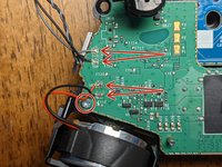
The wires will need to be desoldered from the board, and will be replaced later for reassembly.
-
Note: each pair of wires has the black cable soldered to the lower connection; keep this in mind for the reassembly if the pictures from this guide aren't nearby.
-
Note: You may be able to get away without desoldering these, depending on what you need to reach (credit to @bikemerlin), but due to the simplicity and fragility of these connections, I would suggest removing them to prevent additional damage.
-
Some of the solder in this controller requires a very high temperature to release. I had mine set to 450 C, however you may be able to remove it at a lower temperature.
-
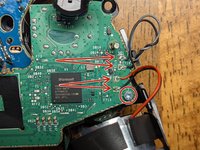
Remove the two T-6 screws from the board near the vibration motors.
On reassembly, after the board is aligned over the pins, and screws are started, press in the center of the board mother board to plug in the connector from the motherboard to the button board.
Getting in here to clean a sticky Y button, i was able extricate the button board without de-soldering any of the wires. Unclipping the black/gray wires from their most outboard clips and then being extremely careful not to bend any where they connect to the motherboard, you can flip the whole motherboard out of the way, giving enough access to the button board.
Yep, it should be possible to do it without desoldering. Some of the other main board connections are quite a bit more difficult to desolder, but these are relatively easy in comparison, so I would still suggest removing them to prevent extraneous damage if at all possible; assuming you have the appropriate tools, of course!
That's my bad soldering job - I had a time with some desoldering and got a bit frustrated at times. These connections weren't bad to work with, but that doesn't prevent me from being bad at soldering lol
Note: T6 screws are not security bits.
If that's in regard to the tool requirements, I think the tools I could choose from in the UI either didn't have it or there were T6S somewhere else in the controller, however, I don't see what you're specifically referencing. For anyone needing the tools to do this, T6S (security) tools will work with T6 hardware, but not the other way around if you encounter T6S hardware and only have a T6 bit.
Does anyone know what the IC with W8 attached at FT21 is? This IC somehow sheared off while I was desoldering black/gray combo, no clue how that was possible since I never touched it. But I'm definitely going to swap the component out either way.
-
-
-
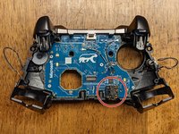
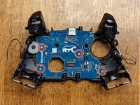
Begin removing the motherboard by sliding it up along the pins (as noted in the picture). The left side will need to be lifted off of its pin and the board rotated counter-clockwise at a slight angle before it will be able to slide the remaining distance off of the right (longer) pin.
-
The triggers will flex up a bit which allows a little extra room for the board. As with everything else in this disassembly, use caution and patience to prevent damage to any of the components.
-
Once the motherboard has been removed, you may have already noticed the headphone jack has moved or fallen. If it hasn't remove it from the board now.
Be careful as you slide up the motherboard, as there is a connector between them, and can easily shear the connector on one side if not slow and careful.
-
-
-
There are two tabs holding the retainer for the bar in place. Gently pop these toward you with a spudger and they'll slide up from their own tension. Note: the retainer will likely stay attached to the bumper assembly, but must be removed from the main controller assembly before proceeding to the next step.
-
Once the retainer has been released, again use the spudger to gently pry the buttons outward and upward (in the direction of the arrow in the image) which will release them from another clip. Do this on both sides.
It’s worth emphasizing that these retainers are fairly easy to break on accident. Be extra gentle when removing or replacing the bumper bar.
Thanks for the advice; I’ve updated the guide to reflect!
So... I did break one.. is there a replacement?
The bumper bar comes as an assembly from everywhere I've seen, so it's likely you'll need to purchase a new assembly or scavenge one from a parts controller.
-
-
-
Remove the four T-6 screws holding the daughterboard to the controller frame. Keep in mind this board holds all of the remaining buttons in place, so be careful none of them are lost when removing this.
-
Note: All of the buttons have clips surrounding them that prevent any of the buttons from being installed in the wrong place; be sure not to force any of them into a different location when reassembling the device.
-
When reassembling, do not force anything into place as this could indicate something has been installed improperly.
-
That's it! Hopefully this guide allowed you to access any components that need replacing.
This is also known as the "button board"
Talking about every step except the D pad. I have a problem only with the d pad
This is a disassembly guide and to this point, the directional pad has already been removed. What problems are you encountering?
Mine is brand new, BUT, the left joy stick STICKS to the left full on a lot. Sometimes to the right as well.
There's nothing causing it to recenter.
No I can't take it back, messed that up like a moron I'm stuck with it.
The joysticks are an absolute pain to remove, but if you can remove them, they are easily replaceable. Basically, the solder on all of the connections must be melted concurrently for its connection to the board to be removed. If you manage to do this, you've done the hardest part; beyond that, you need only to solder each connection as you would any other. The caveat is there are unique deadzones to each joystick assembly that either need to be matched closely or calibrated with additional hardware as I don't believe MS has or ever will release any way to calibrate them.
This is AWESOME information! Perfectly detailed, clear and to the point. You have a gift for communication, a rarity these days. I also appreciate your follow up to user Q/A's. Thank you & cheers 🥂!
-


To reassemble your device, follow these instructions in reverse order.
To reassemble your device, follow these instructions in reverse order.
İptal et: Bu kılavuzu tamamlamadım.
22 farklı kişi bu kılavuzu tamamladı.

23 Yorum
Hi Wayne,
thank you for the guide.
I have an issue with my controller and I can’t find the answer anywhere so here’s hoping maybe you could help me.
In shortest trigger movement setting (hair triggers) I can press LT and the movement is restricted as it should but software doesn’t registered the button as fully pressed. In Xbox Accessories I can see that the controller thinks I’ve pressed the button at around 30%.
I assume this is a hardware issue but I’m not sure which part I should be looking at. I’m a beginner tinkerer :)
Off-hand, I don't know how the controller is doing this unless it's using 3 different potentiometers per trigger. I'd be willing to bet the problem is with software though because I've had the same problem in the past, but never really looked into it. I just checked mine now and it shows the hair-triggers to be working as expected in all positions; I checked these in both the Xbox Accessories app and Windows controller settings. Instead of tearing down the controller as a first step, I'd try checking for updates with everything: Xbox Accessories, Windows, the controller firmware, and the Windows driver for the controller specifically. If any of those have an update, restart your computer (after any single update) and then re-check all of them for updates again. If that doesn't work, let me know and I can try checking into my controller components to see what all compose the trigger assembly since I need to replace a couple of buttons that are wearing out anyway!
I have tried updating firmware of the gamepad but 5.11 and beyond does not really work well on Win10 and Bluetooth (Xbox Elite 2 is recognized as standard Xbox controller and paddles don't work). However, I did verify that I encounter this issue on 4.8 (bluetooth and cable) and 5.13 (cable).
I have reverted the firmware back to 4.8. I have deleted and reinstalled Xbox peripherals drivers as well as uninstalled most Human Interface Devices drivers & restarted my PC. Didn't help.
I took screenshots hoping this would clarify my issue:
https://ibb.co/8jK5bMS - RT is in hair-trigger (shortest movement), RT is registered as fully pressed
https://ibb.co/gTcWgWG - LT is also in hair-trigger, here I'm pressing LT as hard as I can but it's registered as ~35% pressed
https://ibb.co/9wfzDMR - gamepad tester tells me that the button is not pressed fully
It'll be a few days before I can tear my controller down, but just to confirm, your right trigger is working fine and it's just the left trigger not registering the hair-trigger switch?
Yes, RT is working fine. LT works correctly in a sense that I cannot press it fully due to hair trigger lock but the press doesn’t fully register. Are there any sensors there responsible for analyzing strength of the press? The button is analog so maybe there’s something…
It’s worth adding that this has started happening after I gave the controller to 3rd party retail for LB/RB exchange. I cannot establish if they really did change the bumpers or just opened the gamepad and removed these white plastics (but I don’t see the plastics anymore).
Sorry for the late reply! Alright, I just had a chance to break down my controller again and on the back panel where the aforementioned trigger switches are, there are two daughterboards; one for each hair-trigger assembly. I'm not seeing one easily with a quick google search, but if you can find a donor to test it against, you can compare and see if that board is the problem. None of those components require soldering, but you'll need a T3 Torx to remove them. If you have a friend with the same controller, you could try asking them if you could borrow it to test the components (assuming theirs is working correctly!). Alternatively, you could try finding a "parts only" sale on eBay as a donor that might be just as cheap as buying the board, but it might be a gamble as to whether or not it will have good parts.
Regardless, as a first step, I'd just pull the controller apart and see if there is any obvious damage or loose connections; good luck!
Oh, as a side note: those white plastics aren't 100% necessary for the bumpers to function. If I were to guess, I'd say they are probably to prevent excess friction/damage to either the bumpers or switches, but as easy as they are to replace (in general), I wouldn't worry about it.
Is there anything in the guts that identifies what kind of plastic the controller is made of? Like a sticker or something molded into the inside that isn't visible in the photos? I don't see anything listed in the manual but I could have missed it.
Particularly the faceplate; I just want to pop it off to paint it, but I'm having difficulty finding information about what kind of plastic they used.
Edit: I know the center part looks like it has ABS stamped on it, but I'm not sure if the same plastic was used for the front and back pieces as well.
I know this is a late reply, sorry for that, but without knowing what type of plastic it is I would suggest:
- test painting a few small areas inside the controller housing to see how the paint holds to the surface
- test painting a small portion on an inconspicuous area of the controller where your fingers consistently rub (probably on the back where a finger regularly rests)
- coupling these tests with any type of primer or paint adhesion material
Hopefully you were able to find an answer before now, but if not, this strategy might work. Good luck!
hi wayne, thanks 4 the tuto, greetings from Mexico!
Hi Jesus, thanks and greetings from Indiana!
Sagt mal wofür sind die beiden Kabel die die. Boards verbinden? Eins ist mir abgerissen aber es funktioniert alles. Oder sind es nur Antennen?
Ich kann nicht sicher sein, aber ich denke, das ist eine gute Annahme. Sie scheinen nur ein geflochtenes Kupferkabel zu sein und die Anschlüsse ähneln Antennenanschlüssen, die ich in der Vergangenheit gesehen habe. Wenn deins immer noch auseinandergenommen ist, könntest du die Theorie testen, indem du den Wireless-Dongle benutzt und versuchst, ihn kabellos zu verwenden, während beide abgesteckt sind, und deinen Abstand zum Dongle erhöhst. Schön, dass es zumindest mit dem einen noch funktioniert!
Hello Wayne, hello community,
I came across this page during my problem and my research. Perhaps one of you has a solution or a tip for me. I replaced the original joysticks with a Hall effect joystick. Unfortunately, the controller has not shown any signs of life since then. It won't turn on, no light comes on and no tool recognizes the device. I have checked everything several times but cannot find anything that is causing this problem. Has anyone else had this problem and can give me a hint as to what I am doing wrong or what might be defective? I would be very grateful for help. Kind regards, Nadine
This text was translated by Google Translate
I have yet to try this mod on my controller, but I would like to at some point in the future. The only thing that immediately comes to mind is that the output of the hall effect joystick has a different output from the original potentiometer joystick; I think this is an inconsistency of resistances and total values, but I'm definitely not familiar enough with this to confirm. I would look into the values that the hall effect stick provides and compare them to the values that the original potentiometer stick provides; this might cause some kind of firmware protection error that prevents the device from booting, although again this is just a guess as I'm not entirely sure. If you find anything out, I hope you'll share it with the community as hall effect sticks are a much better technology that should be easily usable in our overpriced controllers that fail far too early.
Hi just wondering if anyone has an answer. my controller will only stay on for a max 5 seconds and the xbox button will only work to turn it off
Does it work with the controller plugged in or is this only a problem with the battery? Have you tried multiple cables? Sometimes cables will appear functioning and seem to charge but not actually work. If you haven't, try at least 5 different cables to ensure the connection isn't being partially refused by either the PC or the controller. Additionally, you may try to charge it with a USB brick (same idea with various different bricks to test) instead of plugging it into a PC.
Hi everyone,
Just a word of advice. I'd be careful with removing the joysticks in step 3. For some reason mine wouldn't budge and finally when I used a little more force on the pliers they just started rotating without unscrewing. They just would rotate around their own axis without unscrewing. Whereas the right potentiometer still works ok after assembly, the left joystick/potentiometer seems to work really choppy. It kind of catches on something and generally is unusable :/
Hola , podríais poner un tutorial para reemplazar la parte inferior de la carcasa ? Estoy intentando cambiarla , y me he encontrado con el problema de unos imanes circulares que están pegados, creo que son para la base de carga
¿Te refieres a la funda de tela rígida que viene con el mando?
I disassembled my controller a few days ago to replace a broken joystick. After doing so i put everything back to gether correctly but when i tried turning on the controller it did nothing. Though when i plug it in to a power source it vibrates once then does nothing. Ive tried seeing if any connections were severed or if the battery needed to be replaced. Nothing worked. Does anyone have any idea what the issue could be?
Could possibly be a bad contact internally. I just did a tear-down of mine and noticed there are a few contact points between the boards and a few more on/around the battery housing. Maybe a factory defect or junk battery. The one I'm working on is actually my 2nd series 2. The first one I bought lasted a whole 2 weeks before the sticks began drifting so bad that I couldn't even turn the controller on and scroll through menus or anything. The 2nd one, if I remember correctly, may have been damaged during a "rage quit" moment and now the outer casing (front & back) need to be replaced. I may have been the fact of the rubber grips peeling off that contributed to the rage of the moment. Will soon be ordering new casings WITHOUT rubberized grips.
BTW, my Series 2 controller is several yrs old by now and amazingly still had enough charge to turn on after sitting in a box for yrs...
Starting center to sides from top, then center to sides from bottom worked for me.
Robert Cole - Yanıt