
Xbox One Wireless Controller Model 1708 Button Replacement
Giriş
1. adıma gitThe Front Buttons on your Xbox Controller could become unresponsive or sticky. If this happens it could be necessary to remove the Front Buttons to either replace or clean them. This guide will teach you how to access and replace the Front Buttons on your Xbox One Wireless Controller Model 1708.
Neye ihtiyacın var


-
-
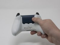
Slide the battery cover toward the top of the controller to remove it.
-
Lift up the batteries or the battery pack from the battery compartment.
-
-
-
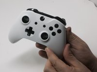
Insert a plastic opening tool into the top seam, and gently work the opening tool to the bottom of the controller.
-
Continue using the opening tool to gently pry the side plate off of the controller.
-
Repeat this process for the second side plate.
Only use a pry tool! The vibration motor wires are exposed and directly accessible from the side when opening. I attempted to open it with a small knife, expecting to be able to gently pry the clips open, accidentally sliced through my right motor’s wires.
If you have some Guitar picks laying around they work GREAT!
For some reason, the two closest hinges at the top of the two handle covers are extremely strong. I had to play around to get them off unlike several guides and video tutorials that, I don't know how, take them off without the slightest effort.
Controller wireless Xbox One Model 1708 -
-
-
Gently peel the battery label or punch a hole in the center of the sticker in the battery compartment to reveal the hidden screw.
-
Remove the five 9mm torx-9 security screws from the back of the controller.
Since mine is out of warranty I just broke out the security nib with a 2.0 standard bit. Then used a T8 torx.
-
-
-
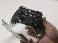
Turn the controller face down and gently lift the rear plate.
-
-
-
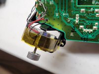
Tape the Rumbler/shock motors in place.
-
This will prevent the motors from falling out.
if you replace thumbsticks only, this step is NOT required and it is safer not to remove bottom cover, removing faceplate is sufficient to replace thumbsticks
-
-
-
Turn the device over and remove the directional pad by gently pulling it away from the controller.
It needs to be made a little clearer that the thin metal retaining ring needs to be unclipped before pulling on the D-pad. A small, flatbladed screwdriver did it nicely for me.
As mentioned above, clarification is needed that the metal ring is intended to lay on top of the DPad - you should remove it first when disassembling, and it should be installed after the DPad to hold the DPad down when re-assembling.
Additionally, the DPad is oriented so that the directional button without an extended tab on the end is on the bottom (down).
This step is not necessary if you are removing the top motherboard for replacing the joysticks as the D-pad is part of the bottom motherboard.
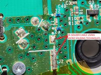
In the case of replacing the joysticks (adding in hall effect sensor sticks) I found it useful to desolder all the rumble motor wires before disconnecting top & bottom motherboards. -
-
-
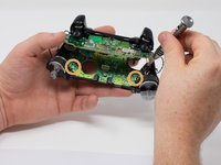
Pull the joysticks off of the controller.
Are the joystick potentiometers soldered to the mother board or just push fit, this guide doesn’t mention soldering so I’m assuming the latter?
Can you get genuine replacement joystick potentiometers as I’ve only seen cheap eBay type ones?
The actual joysticks themselves are soldered into the bottom motherboard.
-
-
-
Turn the device over and remove the two 7mm torx-6 screws in the bottom left and right corners.
What if you don’t care about the rumble motors (always turn that feature off anyway), can I just leave them unattached?
-
-
-
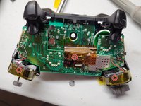
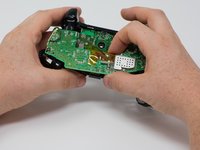
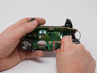
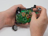
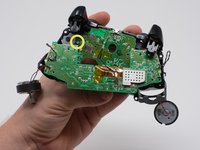
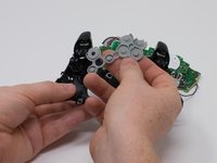
Firmly grasp the top and bottom motherboards in opposite hands, then gently pull them apart.
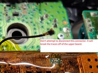
Soldering is not necessary for separation as on the top motherboard it uses a small connector commonly used in wireless assemblies for antennas. Simply pop it of using any prying tool or just your hand but make sure it is the side that has a gold or brassy finish and not a solder joint.
Hey Wyatt,
Thanks for the feedback. I was on the team that authored this guide. I did not work on this specific guide so I am not familiar with this specific connector. I will follow up with iFixIt and check this issue. Thanks for the comment!
Wyatt is correct that the black wire in the center can be removed from the top motherboard, but it doesn’t do any good to do so as there are two other sets of wires (grey and black twisted pairs leading to the left and right trigger) preventing you from removing the bottom motherboard entirely. These wires are visible in the pictures of this guide.
I accidentally broke the part where the black wire connects to. Do I need to buy the top motherboard to fix this problem?
What's is the name of the part for wireless on the controller
In my controller that black cable (the antenna like) was separated form the board is there any way to solder it again (the socket is still conected to plug)
I have the same problem. It popped off the board when firm pressure was applied to reconnect the wire after a repair. I'm going to attempt to apply a small bead of solder to the part that popped off, press it in place, and then heat the connector with my iron. But I am not hopeful at all. It's tight, really tight, and if it works it will be through luck alone.
Any luck? Theres no pad to get the solder to stick to on mine. Im assuming it is the j1 connection. Any idea what this wire is for?
Same issue here. I tried to unplug the antenna connector but the weak solder joints disconnected from the top motherboard instead. Looks like it has couple of bigger solder pads for ground/shielding(?) and one tiny pin in the middle for the actual antenna which can maybe still connect by pushing in place? Looks like a very difficult solder job as everything is so tiny.
Hi i destroy black wire connector on top board please help me.
It’s IPEX 4 connector, i've ordered bunch on chinese site and replaced mine. It was hard but doable.
mntlzr -
mntlzr : Thanks a lot for the connector type. More specifically it seems to be IPEX 4 SMD female socket on the top motherboard.
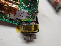
Hi yellow tape on board what
Looks like thick Kapton tape. Probably meant for electrical insulation and a barrier for the coaxial cable to rest on instead of sitting directly on SMD components (which are under the tape)
How does the black wire reconnect? And is it necessary?
I just put my controller back together (I opened it just to clean all the buttons since my son spilled some juice on it) and it seems to work wirelessly (with a PC using the dongle that came with the controller) even having broken the small black antenna cable connector off from the top motherboard. Not sure what that cable is used for or is it just an additional antenna for better connectivity. At least my controller still seems to work fine wirelessly without that cable being connected even from several meters away from the computer.
Actually nvm. Now that I tried the controller for a second time on the next day it seems to disconnect all the time so wireless is not working properly. I’ll need to try to fix the antenna cable by soldering. Probably will order a replacement connector (IPEX 4 SMD female socket) and try to solder that on.
I think I broke off a little bit of the black antenna. In the zoomed in shot it showed a tiny little piece of wire soldered on the pad with Z2 above it but mine wasn’t stuck onto it. I see a little white (plastic I think) nub on the end of the wire. My controller’s bluetooth range now is only a foot. What do I do? Do I just replace the cable or can I melt away the plastic material and bridge it with solder?
1) TAKE HEED TO THESE WARNINGS AND BE VERY CAREFUL
2) Instead of separating the boards completely all you need is to get enough space to pull the part out.
*WHILE HOLDING WITH BOTH HANDS AS IF YOU WHERE PLAYING AND PUSH THE TOP BOARD FORWARD WITH YOUR THUMBS LIKE A DRAWER AND THEN LIFT UP!
IT WILL SEPARATE JUST ENOUGH TO DO WHAT YOU NEED. *THIS TAKES CARE, FINESSE, & SOME SKILL.
This entire step is asinine. 1: you don't need to completely separate the two boards in order to pull them as a single assembly from the controller. 2: Why the f would you try to get someone to do solder work just to clean up some buttons?
Just got done putting mine back together after cleaning("Y" was sticking). I was able to access all screws without completely desoldering, no broken wires. It wasn't even hard to do. As long as you don't try to force anything, it's easy.
This isn't the first iFixIt guide that has made me go "WTF? You're overcomplicating things!" either. It is a running issue with their guides.
There is a tool designed specifically for that type coaxial connector (UMC extraction tool)
https://www.digikey.ca/en/products/detai...
However, you can usually safely remove that coaxial cable by hand or with a spludger tool or small flathead screwdriver. The trick is to wedge between the ground fins of the receptacle (longer solder sides of the connector on the PCB) and the coaxial plug/head, pushing off of the ground fin to nudge the plug up and away from the receptacle. The receptacle solder pads can be weak and if you arent careful you can easily break the receptacle and plug off together. Just take your time and use the ground fins to push against so that it holds the receptacle down while lifting the plug up. Might have to pop one side then pop the other side (always using the ground fins as a fulcrum point). -
-
-
Remove the audio port from the bottom mother board.
Can you just leave out the audio port and use the controller or u have to have a replacement to play
Why would you *need* the audio port? If you are happy to not use then fine, this is an instructional to get it working and by extension a headset one would assume.
Ali J -
This piece is just placed in there - sandwiched between the two motherboards. No adhesive, no mechanical attachment, nothing.
So can it be replaced or no? I took it out it dont look fried or anything but it still dont work when reinstalled
-
-
-
Remove the three 70mm torx-6 screws from the center of the bottom motherboard.
-
Remove the two 70mm torx-6 screws next to the rumble motors on the bottom motherboard.
-
Remove the one 70mm torx-6 screw located on the left side of the bottom motherboard.
-
-
-
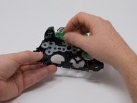
Use a plastic spudger to lift the plastic clip off the front pegs.
-
Remove the plastic clip by sliding it upwards.
Reassembly: This hard is hard to mount. Slowly flip the controller upto view the charging port and notice it isn’t aligned yet… If you force it to outside of pcb, it’ll try to pop off. I’ve yet to figure this step out… I forced it and after full reassembly, the bumpers became REALLY stiff.
Solution: Instead remove the outside piece mentioned in image… then remove the bumpers… Check that all cavities are clear. Then make sure the sync button is inserted all the way in… Then place the left bump in the far left hole first. Then ensure the horn part slides into it’s specific slot inside, then ensure the the sync button goes in hole…then continue to right bumper side…. Then add the over cover piece above it… Start with the piece that goes over the charge port. Then the front as the above image shows… Now check your bumpers for easy clicking… If it’s still not correct, remove and try again gently as the horns may snap off and the PCB may get damaged.
Note: I believe the order is very important or the alignments on the left side may have the horn forced into one of the other close cavities and you won’t even know it. (This causes that horn to get damaged over time too. Without the horn, the bumper will drift and miss the button and bind up the trigger.)
-
-
-
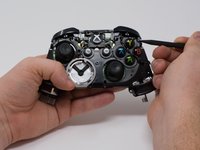
Use a spudger to release the small hooks at each end of the left and right bumper.
-
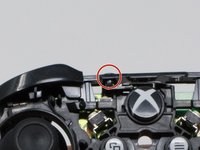
After you release these hooks, be careful as you separate the face plate from the back of the controller. The connect/sync button (see second image) is held in by this face plate and will come loose as you perform this step.
Watch for the tiny button that sticks out from the top - it’s the wireless connect/sync button. It will fall out and is easy to lose. During reassembly, I found it easier to put the bumper back in first, then use a tweezers to insert the button back into place.
-


To reassemble your device, follow these instructions in reverse order.
To reassemble your device, follow these instructions in reverse order.
İptal et: Bu kılavuzu tamamlamadım.
58 farklı kişi bu kılavuzu tamamladı.
Ekip

Cal Poly, Team S18-G3, Forte Fall 2017 Cal Poly, Team S18-G3, Forte Fall 2017 üyesi
CPSU-FORTE-F17S18G3
4 Üyeler
37 adet Kılavuz yazıldı
8Kılavuz Yorumları
Thanks for the contribution for you and helped a lot of people.
You don't need to desolder anything to remove the top motherboard!
Those black and grey wires go to the vibration motors in the triggers. Remove the covers on the triggers along with the motors, and carefully remove the wires from clips on the front of the controller. Make sure you get the black signal wire. You can now safely remove the two boards from eachother.
I needed a guide for this because my “X” button was sticking and I ended up doing the whole thing without separating the motherboards, cleaning everything that touches the button, and it worked like a charm. Thank you very much for the guide!
I wore out both the sticks playing COD, this helped me to make it usable enough for P2. cheers!
Just a heads up for people, there is an antenna wire that the guide leaves, takin it off the top board make your life easier and is very easy to put back on
Good easy to understand guide. 5 stars from me definitely