
iBook G4 12" 1.33 GHz Optical Drive Replacement

Giriş
1. adıma gitUpgrade or replace the CD, DVD, combo or SuperDrive.
Neye ihtiyacın var
Parçalar
Aletler


Daha fazlasını göster…
-
-
Lay your iBook upside down on a flat surface.
-
Use a coin to rotate the battery locking screw 90 degrees clockwise.
-
Lift the battery out of the computer.
-
-
-
Pull the keyboard release tabs toward you and lift up on the keyboard until it pops free.
-
Flip the keyboard over, away from the screen, and rest it face-down on the trackpad area.
-
-
-
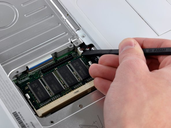
Pull the keyboard cable up from the logic board, holding the cable as close to the connector as possible.
-
-
-
Use a spudger or small flathead screwdriver to remove the three rubber feet from the lower case.
"Close the display and flip the computer over." ...Seems like this instruction ought to be at the beginning of step 1 rather than step 2. In step one, the display is already closed and the computer flipped over. In step 2, you just keep it in this position and proceed from taking the battery out to removing the rubber feet.
Well, if you've had an iBook G4 this long, odds are the little rubber feet are falling off just from being looked at. Except the battery mounted one. That sucker is the Devils' Tower of little rubber feet.
-
-
-
Remove the three Torx screws using a T8 Torx screwdriver.
it seems a little bit weird to be using a Torx Screwdriver (T8 or T9 as the case may be) to remove hex screws. My machine has Torx screws in these locations.
Definitely haha- I checked the picture and those are definitely hex screws.
-
-
-
Push the thin rims of the lower case surrounding the battery compartment in, bending them past the tabs, and then lift up to free that corner of the lower case.
I find that a stiff nylon guitar pick will work if you don't have a spudger.
Definitely read the rest of the instructions now. I struggled at first... I was using my ipad with the step by step instructions and didnt scroll down past this photo, so I didnt see the sequence of how to loosen the tabs. in fact I didn't know where the tabs might be... Only discovered that part when I reassembled it. The spudger didn't work for me. Too soft, I used mostly a thin very small screwdriver.
-
-
-
Run a spudger along the seam between the lower case and upper case on the front of the computer to free the tabs locking the lower case. Pull up on the lower case and continue to use the spudger as necessary until you hear three distinct clicks.
-
-
-
There are three tabs over the optical drive that must be released before the lower case can come off. Slide the spudger into the lower case above the optical drive and run it toward the back of the computer until you hear three distinct clicks.
try using the spudger at the back near the vents. To be specific, on the left side of the hinge when faced upside-down. It's easier this way and it's described on Apple's official repair manual.
then put a library card or something between the outer enclosure and the optical drive enclosure then pull from the other side to free the casing
-
-
-
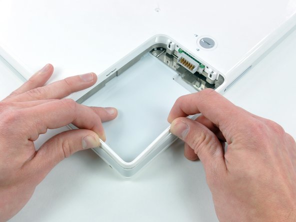
Turn the computer so that the back is facing you and pull the lower case up and toward you until the back tabs pop free.
Removing the back cover at this final step was had for me; I had to use a flathead screwdriver to separate the back edge of the cover away…I was not able to separate the lower case all the way by pulling the lower case up and toward me as shown in the photo.
-
-
-
Remove the following 4 screws from the bottom shield:
-
Two 3 mm Phillips.
-
Two 7.5 mm Phillips.
-
-
-
Remove the two Phillips screws securing the DC-In board, removing tape as necessary.
Be careful here as the actual DC silver connector is raised from the chipboard so once you remove the screws use the spudger to gently lift out the DC IN board itself. There's some rubber casing around the silver connector too which got caught on the plastic casing of the laptop which required a bit of gentle poking to get free...
Is it necessary to remove DC cable?
@rickyzhang Yes, in order to remove the top case, this is required.
8 Bit Guy clearly bypassed that step somehow. https://www.youtube.com/watch?v=52-nCu2w...
-
-
-
Deroute the cable from around the optical drive, removing tape as necessary.
-
Disconnect the DC-In cable from the logic board and angle the DC-In board out of its compartment.
Also, once I removed it, I thought there was more to do. It happened so quickly and effortlessly! I kept wondering when the difficult and trying part was coming. I was kind of disappointed by the lack of the challenge, but that's OK! The difficult part came from reversing the directions and getting the shield back in place. A cable covering on the back edge under the shield slipped out and prevented the metal tabs from seating correctly. Once I figured that out, it was smooth sailing!
Why? It‘s not necessary
-
-
-
Remove the two 3 mm Phillips screws inside the left edge of the battery tray.
-
Three 3 mm Phillips around the battery compartment.
-
Three 4.5 mm Phillips along the optical drive bezel. (a magnetic screwdriver may help to lift these screws out)
-
One 12 mm Phillips in the lower right corner.
-
Four 14.5 mm Phillips.
-
-
-
Remove the following 7 screws from the edges of the keyboard area.
-
Three 2 mm Phillips along the right edge.
-
One 4.5 mm Phillips underneath where the magnet was.
-
One 6 mm Phillips with a small head in the lower left corner.
-
Two 6 mm Phillips with large heads, one in the upper left corner and one in the middle.
-
-
-
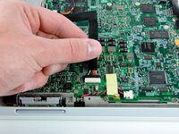
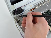
Carefully lift the upper case slightly and move it toward the front of the computer to reveal the trackpad connector. Use a spudger or your finger to disconnect the trackpad connector hidden beneath the white plastic tab.
-
After disconnecting the track pad connector, carefully rotate the upper case away from you and rest it against the display.
Although these instructions forewarn that these connectors are fragile, I would suggest emphasizing this in BOLD. When one of these connectors in the next couple steps pulls free from the logic board, as my speaker connector did with very little force, I was told by my Mac repair center that "...you're at the end of the road, period. There's no way we can re-solder that speaker connection". This may not be totally correct because other advice in iFixit suggests it is possible but regardless, the extremely small contact pads that need to be re-soldered really requires removing the entire logic board, experience with very tiny solder projects, and double the time and effort.
A second tool such as a tiny flat blade screw driver to hold down the connector that is soldered to the logic board while pulling/prying up on the male side of the connector with the spudger so that the soldered portion doesn't rip off the board was found to be helpful.
This set of instructions however is very complete, just read them carefully.
Follow crtolson's advice, but when prying the connectors, do it one side at a time, and use a LIGHT touch when doing so. Work each side slowly, HOLDING DOWN THE HEADER IN THE CENTER WITH A SMALL FLAT-HEAD PRECISION SCREWDRIVER, pulling up lightly with the spudger once per side. The connector will eventually come loose enough to lift it from the header. DO NOT USE YOUR FINGERS! Always use a spudger.
The instructions in CAPS are VERY important, lest you pull the header off the board. I've made this mistake myself, and I've been working on Mac notebooks for 20 years...
Prying with spudger... Connector "walked out" with socket on logic board.(contacts were intact, solder is pretty bad after those years)It is like a lottery. I had to use great force to separate these two afterwards.
-
-
-
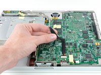
Use the sharp end of a spudger to disconnect the speaker cable connector.
The speaker cable connector was very tightly connected into the socket. When I tried to take it out the socket came right off the motherboard. In this case, in order to pull out the connector plug you must hold down the socket at the same time to make sure it isn't pulled from the motherboard.
i got a used book and opened it to exchange the hd to a bigger one. i found the airport/bluetooth cards connective socket dislocated and the speaker cables' socket as well. now i've led the free end of the speaker cable together with its connector through the opening of the kensington lock outside the case (no easy task but it went through) to fix a jack which goes into the headphones plug.
The male connector came out with the female one right off my logic board. I tied very carefully gluing it back. Appears that isnt enough; will need to be soldered back into place if I aver want to have sound again. USB, Bluetooth or AirPlay/AirTunes seem to be my remaining options.
Be very careful with this step!
-
-
-
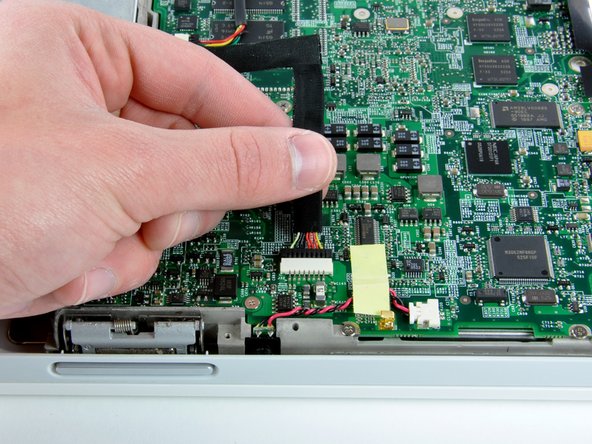
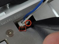
Using the sharp end of a spudger, disconnect the connector for the blue and white power cables. Again, be careful to pry up only on the connector.
-
The upper case is now free and can be removed from the computer.
john50 kullanıcısından alıntı:
There is actually no need to remove the power plug if you are careful with the placement of the top cover. I had the whole plug pull of the board and had to solder it back again. Not an easy task had to use a magnifying glass to see it.
I wish I had read John's comment! I thought I was being careful to unplug without pulling and I pulled the whole plug out of the board too : ( I've never soldered anything before.......
john50 kullanıcısından alıntı:
There is actually no need to remove the power plug if you are careful with the placement of the top cover. I had the whole plug pull of the board and had to solder it back again. Not an easy task had to use a magnifying glass to see it.
As noted above, be very careful!
I also had the whole plug come off the board and had to solder it back. Definitely try and do it without removing the blue & white power cable.
Ditto. I didn't even notice that I'd torn the connector off the logic board until I went to put it all back together. It really is way too tight a connection and since you have so little room to work, it's VERY hard to pull it out without damage.
If you break this connection, anything else you're doing won't matter. Go slow, get a magnifying glass and perhaps try to hold town the part that's connected to the logic board as you attempt to pull out the connector....
If you have any problems or think that you can't do this, I'd say that you should stop, button it all back up and bring it to someone. Even a cheap, used logic board is around $250-350 -- and that's not worth it.
Matt kullanıcısından alıntı:
As noted above, be very careful!
I also had the whole plug come off the board and had to solder it back. Definitely try and do it without removing the blue & white power cable.
Several people have mentioned soldering the plug back.......How exactly did you achieve this?! Are you experienced with micro-soldering? Were you able to salvage your laptop?! Although I got good advice to take it to a tv/electronics shop and have them solder the blue and white cables directly to the board, I have not done this. The comp is still neatly packaged by teardown step and sitting in a cardboard box. It's really annoying to look at this useless box of components that used to be a very nice little laptop : (
I would love to hear how you managed the repair.
Ann
Ann kullanıcısından alıntı:
Several people have mentioned soldering the plug back.......How exactly did you achieve this?! Are you experienced with micro-soldering? Were you able to salvage your laptop?! Although I got good advice to take it to a tv/electronics shop and have them solder the blue and white cables directly to the board, I have not done this. The comp is still neatly packaged by teardown step and sitting in a cardboard box. It's really annoying to look at this useless box of components that used to be a very nice little laptop : (
I would love to hear how you managed the repair.
Ann
The plug has two holes in the back that slot into two pins on the board.
I slotted the pins in and the two wires on the front of the plug that need soldering to the board line up where they attach to the board.
I used a soldering iron with a flat tip (like a flat-head screwdriver) and pressed on the two wires at the same time for a second or two. That was long enough to melt the solder and reattach the wires. It took two attempts to get it attached correctly.
I didn't add any extra solder and I haven't had much experience with soldering.
Matt kullanıcısından alıntı:
The plug has two holes in the back that slot into two pins on the board.
I slotted the pins in and the two wires on the front of the plug that need soldering to the board line up where they attach to the board.
I used a soldering iron with a flat tip (like a flat-head screwdriver) and pressed on the two wires at the same time for a second or two. That was long enough to melt the solder and reattach the wires. It took two attempts to get it attached correctly.
I didn't add any extra solder and I haven't had much experience with soldering.
Ann kullanıcısından alıntı:
Thanks Matt! That was a very complete description. My son (mechanical engineering student.....unfortunately, not electrical...lol) has some equipment. I'm hoping that he can manage it when he comes home this weekend. I do see the pins on the board and the two wires.
Thanks again sharing your approach!
Ann
JCarlos19 kullanıcısından alıntı:
Be careful with this step, when I did I was stuck with glue on the cable connector of the card.
DO NOT PRY!!!! just toasted my iBook following this lousy advise. Try pulling from the wires very lightly instead or cut back the surrounding metal to get a better approach. If anyone has a high res scan of the area surrounding the the plug and where to solder connection, I melted the socket and am now resorting to soldering directly to the board but its not going well.
this is a very tricky step
Man, this step is really hard. The hardest step of the iBook guide. It is possible to carefully wiggle it out. Bit by bit, wiggle the plug gently back and forth ever so slightly, so that it comes out. It is SO easy to break it. I've done it before. With patience, it can be done. Just take your time.
If you're careful and are able to remove the trackpad connector without damage, it is possible to lean the top case and metal shield against the screen, without having to remove the speaker and power connectors, while you replace the hard drive. You'll have to unstick the speaker cable from the shield first, remove the screws, and reroute the speaker cable out of the notch that it's in. SLOWLY remove the metal shield and CAREFULLY lean it up against the screen.
Say: wouldn’t it be a Good Idea to simply snip these wires a few inches from the connector, and twist the darn things back together? Don’t touch the delicate little plug! If you’re fussy & neat, the wires can be soldered & shrink tubing slipped over them. Note: I have a G4, but I have NOT done this work ( yet! ) Still…isn’t my idea pretty good?
It is pity iI have not done that. Connector survived, but it wiggles and definitely not making good contact.(laptop refuses to power on)
-
-
-
Remove the fifteen 3 mm Phillips screws securing the top shield to the computer.
-
Remove the following 16 screws:
-
Thirteen 3 mm Phillips.
-
One 3 mm Phillips. (actual screw not present in image)
-
Two 4 mm Phillips.
-
-
-
Remove the following 4 screws:
-
One 3 mm Phillips in the channel between the optical drive and fan.
-
Two 6 mm Phillips from the upper and bottom end of the drive bezel.
-
One 6 mm Phillips with a collar from bracket extending from the lower left corner of the drive.
-
-
-
Remove the two Phillips screws securing the metal bracket and cable to the back of the optical drive.
-


To reassemble your device, follow these instructions in reverse order.
To reassemble your device, follow these instructions in reverse order.
İptal et: Bu kılavuzu tamamlamadım.
23 farklı kişi bu kılavuzu tamamladı.
