Bu sürüm, hatalı düzenlemeler içerebilir. En son doğrulanmış bellek kopyası dönün.
Neye ihtiyacın var
-
Bu adım çevrilmemiş. Çevrilmesine yardım edin
-
Press and hold down the small round button on the back of the Joy Con controller.
-
While you hold down the button, slide the controller upward.
-
-
Bu adım çevrilmemiş. Çevrilmesine yardım edin
-
Continue sliding the Joy Con upward until it's completely removed from the console.
-
-
Bu adım çevrilmemiş. Çevrilmesine yardım edin
-
Use a Y00 screwdriver to remove the four 6.3 mm-long screws securing the rear panel.
-
-
Bu adım çevrilmemiş. Çevrilmesine yardım edin
-
Use a JIS 000 driver or an official iFixit PH 000 driver to remove the following screws securing the rear panel:
-
One 2.5 mm-long screw on the top edge of the device
-
Two 2.5 mm-long screws on the bottom edge of the device
-
-
Bu adım çevrilmemiş. Çevrilmesine yardım edin
-
Use a JIS 000 screwdriver or an official iFixit PH 000 driver to remove the two 3.8 mm center screws on the sides of the device (one on each side).
-
-
Bu adım çevrilmemiş. Çevrilmesine yardım edin
-
Use your finger to flip up the kickstand on the back of the device.
-
-
Bu adım çevrilmemiş. Çevrilmesine yardım edin
-
Use a JIS 000 screwdriver or an official iFixit PH 000 driver to remove the 1.6 mm screw in the kickstand well.
-
Close the kickstand.
-
-
Bu adım çevrilmemiş. Çevrilmesine yardım edin
-
Open the game card cartridge flap.
-
Lift the rear panel up from the bottom of the device and remove it.
-
-
Bu adım çevrilmemiş. Çevrilmesine yardım edin
-
Use a JIS 000 screwdriver or an official iFixit PH 000 driver to remove the 3.1 mm screw securing the microSD card reader to the device.
-
-
Bu adım çevrilmemiş. Çevrilmesine yardım edin
-
Use your fingers or a pair of tweezers to lift the microSD card reader straight up from the device to disconnect and remove it.
-
-
Bu adım çevrilmemiş. Çevrilmesine yardım edin
-
Use a JIS 000 screwdriver or an official iFixit PH 000 driver to remove the six 3 mm screws securing the shield plate to the device.
-
-
Bu adım çevrilmemiş. Çevrilmesine yardım edin
-
Use your fingers or a pair of tweezers to peel back the piece of foam on the top edge of the device near the fan exhaust port.
-
-
Bu adım çevrilmemiş. Çevrilmesine yardım edin
-
Insert a spudger underneath the shield plate along the edge of the device.
-
Pry up to lift the shield plate and remove it from the device.
-
You can reuse the pink thermal compound if you're careful. Keep the compound clean and make sure it makes solid contact between the heat sink and the shield during reassembly.
-
If you need to replace it, refer to our thermal paste guide to remove the old thermal compound and replace it with an appropriate compound, such as K5 Pro, during reassembly.
-
-
Bu adım çevrilmemiş. Çevrilmesine yardım edin
-
Use the point of a spudger to pry the battery connector straight up and out of its socket on the motherboard.
-
-
Bu adım çevrilmemiş. Çevrilmesine yardım edin
-
Use a JIS 000 screwdriver or an official iFixit PH 000 driver to remove the three 3 mm screws securing the heat sink to the motherboard.
-
-
Bu adım çevrilmemiş. Çevrilmesine yardım edin
-
Carefully peel the two foam pieces stuck over both the heatsink and the fan away from the fan.
-
Insert the point of a spudger underneath the part of the foam that isn't stuck against anything,
-
Press the top of the foam with your finger to hold it in place.
-
Roll the spudger tip underneath the foam all the way to the other end of the foam to release it.
-
-
Bu adım çevrilmemiş. Çevrilmesine yardım edin
-
Use a spudger or your fingers to lift the heatsink up and off the motherboard to remove it.
-
Apply thermal paste to all surfaces that had thermal paste applied previously. This includes between the heatpipe and aluminum shield, which the Switch uses as additional heatsinking.
-
-
-
Bu adım çevrilmemiş. Çevrilmesine yardım edin
-
Use an opening tool or your fingernail to flip up the small, hinged locking flap on the digitizer cable's ZIF connector.
-
-
Bu adım çevrilmemiş. Çevrilmesine yardım edin
-
Use a pair of tweezers to slide the digitizer cable horizontally out of its connector on the game card reader board.
-
-
Bu adım çevrilmemiş. Çevrilmesine yardım edin
-
Use the point of a spudger to pry the headphone jack and game card reader connector straight up to disconnect it from the motherboard.
-
-
Bu adım çevrilmemiş. Çevrilmesine yardım edin
-
Use a JIS 000 screwdriver or an official iFixit PH 000 driver to remove the three 3.1 mm screws securing the headphone jack and game card reader board to the device.
-
-
Bu adım çevrilmemiş. Çevrilmesine yardım edin
-
Use a pair of tweezers or your fingers to remove the headphone jack bracket.
-
-
Bu adım çevrilmemiş. Çevrilmesine yardım edin
-
Use a pair of tweezers or your fingers to remove the headphone jack and game card reader board.
-
-
Bu adım çevrilmemiş. Çevrilmesine yardım edin
-
Use an opening tool, spudger, or your fingernail to flip up the small, hinged locking flap on the LCD ribbon cable ZIF connector.
-
-
Bu adım çevrilmemiş. Çevrilmesine yardım edin
-
Use a pair of tweezers to pull the ribbon cable straight out of its connector on the motherboard.
-
-
Bu adım çevrilmemiş. Çevrilmesine yardım edin
-
Use an opening tool, spudger, or your fingernail to flip up the small, hinged locking flap on the smaller LCD ribbon cable ZIF connector.
-
-
Bu adım çevrilmemiş. Çevrilmesine yardım edin
-
Use a pair of tweezers to pull the ribbon cable straight out of its connector on the motherboard.
-
-
Bu adım çevrilmemiş. Çevrilmesine yardım edin
-
Heat an iOpener and apply it to the bottom edge of the screen for around two minutes to to help soften the adhesive.
-
-
Bu adım çevrilmemiş. Çevrilmesine yardım edin
-
Apply a suction cup to the bottom-left corner of the screen.
-
Pull up on the suction up with strong, steady force to create a gap.
-
Insert the point of an opening pick into the gap, making sure to only insert the pick about 5 mm.
-
-
Bu adım çevrilmemiş. Çevrilmesine yardım edin
-
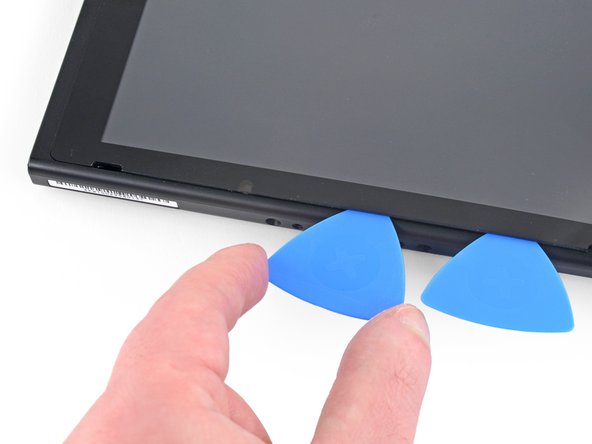
Slide the opening pick along the bottom edge of the screen to slice the adhesive.
-
Leave the pick inserted to prevent the adhesive from re-adhering to the frame.
-
-
Bu adım çevrilmemiş. Çevrilmesine yardım edin
-
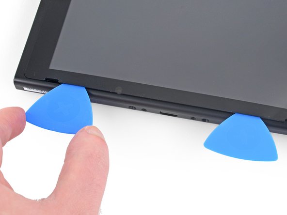
Insert a second opening pick into the gap to the left of the first pick.
-
Slide the opening pick back towards the left side of the device.
-
Leave the opening pick inserted.
-
-
Bu adım çevrilmemiş. Çevrilmesine yardım edin
-
Heat the left edge of the screen for around two minutes to help soften the adhesive.
-
-
Bu adım çevrilmemiş. Çevrilmesine yardım edin
-
Continue sliding the opening pick around the bottom-left corner to slice the adhesive.
-
-
Bu adım çevrilmemiş. Çevrilmesine yardım edin
-
Continue sliding the opening pick along the left edge of the screen to slice to adhesive.
-
-
Bu adım çevrilmemiş. Çevrilmesine yardım edin
-
Heat the top edge of the screen for around two minutes to help soften the adhesive.
-
-
Bu adım çevrilmemiş. Çevrilmesine yardım edin
-
Continue sliding the opening pick around the top-left corner of the screen to slice the adhesive.
-
-
Bu adım çevrilmemiş. Çevrilmesine yardım edin
-
Continue sliding the opening pick along the top edge of the screen to slice the adhesive.
-
-
Bu adım çevrilmemiş. Çevrilmesine yardım edin
-
Heat the right edge of the screen for around two minutes to help soften the adhesive.
-
Place the flat end of a spudger into the gap along the left edge of the screen.
-
Carefully and slowly lift the left edge of the screen, opening it like a book.
-
-
Bu adım çevrilmemiş. Çevrilmesine yardım edin
-
Lift the right edge of the screen straight off the device, threading the ribbon cables through the frame as you do so.
-
-
Bu adım çevrilmemiş. Çevrilmesine yardım edin
-
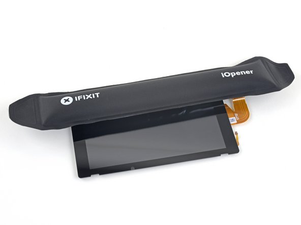
Heat the top edge of the screen assembly for around two minutes to help soften the adhesive holding the LCD panel to the digitizer.
-
-
Bu adım çevrilmemiş. Çevrilmesine yardım edin
-
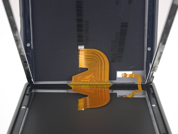
Turn the screen assembly over.
-
Insert an opening pick in between the LCD panel and the digitizer at the top-left corner.
-
Slide the opening pick along the top edge of the screen assembly to slice the adhesive.
-
-
Bu adım çevrilmemiş. Çevrilmesine yardım edin
-
Continue sliding the opening pick along the top edge of the screen to slice the adhesive.
-
-
Bu adım çevrilmemiş. Çevrilmesine yardım edin
-
Heat the left edge of the screen assembly for around two minutes to help soften the adhesive.
-
-
Bu adım çevrilmemiş. Çevrilmesine yardım edin
-
Insert and slide the opening pick along the left edge of the screen assembly to slice the adhesive.
-
-
Bu adım çevrilmemiş. Çevrilmesine yardım edin
-
Continue sliding the opening pick around the bottom-left corner of the screen assembly to slice the adhesive.
-
-
Bu adım çevrilmemiş. Çevrilmesine yardım edin
-
Heat the bottom edge of the screen assembly for around two minutes to help soften the adhesive.
-
-
Bu adım çevrilmemiş. Çevrilmesine yardım edin
-
Continue sliding the opening pick along the bottom edge to slice the adhesive.
-
-
Bu adım çevrilmemiş. Çevrilmesine yardım edin
-
Heat the right edge of the screen assembly for around two minutes to help soften the adhesive.
-
-
Bu adım çevrilmemiş. Çevrilmesine yardım edin
-
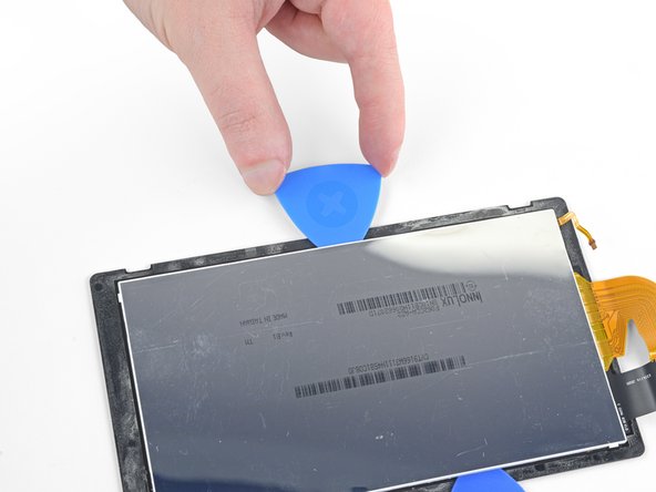
Insert the flat end of a spudger in between the LCD panel and the digitizer along the left edge of the screen assembly.
-
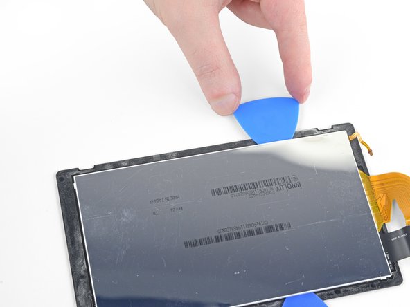
Carefully and slowly lift up the left side of the LCD panel, opening it like a book.
-
-
Bu adım çevrilmemiş. Çevrilmesine yardım edin
-
Continue lifting the LCD panel away from the digitizer to separate the two components.
-


İptal et: Bu kılavuzu tamamlamadım.
56 farklı kişi bu kılavuzu tamamladı.

13 Yorum
I need to buy a new frame for the switch not front or rear panel, where do i get one of these? the vent at the top is broken.
You need the front panel. These are usually sold as a set of the front and back. When you do the replacement, make absolutely sure you transfer the translucent light guide (small piece of white plastic) and the adhesive speaker covers over. One good thing about this replacement is that you don’t have to remove the motherboard or even disconnect the joycon guide rails completely from the middle mounting panel. Take your time, and be very patient. This replacement means detaching the digitizer and screen.
If you can’t find the case here, you might be able to find it on Amazon.
I thought this was going to be hard but compared to automotive this was cake thanks for the guidelines.
Can I use HY-883-4g CPU Thermal Paste Kit-6.5 W/MK CPU Paste instead of the K5-pro thermal paste? Are there other thermal paste recommendations? Thank you.
You can use any thermal paste, if you already got one. If you need to buy one, thek5 pro is our suggestion.