
PowerBook G3 Pismo Logic Board Replacement

Giriş
1. adıma gitIf one of the ports on the back goes bad, you'll have to replace the logic board.
Neye ihtiyacın var
Parçalar
Aletler


Daha fazlasını göster…
-
-
Turn the keyboard locking screw so that it is parallel to the space bar.
-
Pull the keyboard release tabs toward you and lift up on the keyboard until it pops free.
-
Lift the keyboard out by pulling it up and away from you. Rest the keyboard, face down, on top of the track pad.
-
-
-
Remove the two silver Phillips #1 screws that attach the heat shield to the internal metal framework.
-
Lift the heat shield up and pull it toward you.
-
-
-
Firmly grasp the plastic tab attached to the Airport card and pull up and then to the right.
-
-
-
Disconnect the antenna cable from the Airport card.
To disconnect the cable, you just pull on it with enough force. It's just a straight up plug, no special tabs to unhook. I was a little shy as I never want to yank on old electronics, but just slowly turn up the amount of force you're pulling with until it comes loose.
-
-
-
Pull the battery cable directly up from the logic board.
-
Remove the battery from its holder by pulling up and to the left.
-
-
-
Remove the long silver Phillips #1 screw from the heat sink.
-
Remove the two T8 Torx screws that attach the heat sink to the processor.
-
-
-
Grasp the plastic tab on the processor's right side and pull it directly up.
-
-
-
Remove the black Torx screw from the right side of the modem.
-
Remove the small black plastic rectangle with four holes.
-
-
-
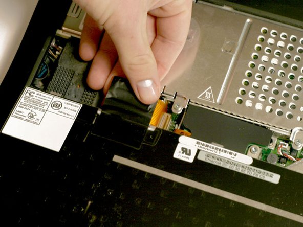
Grasp the orange cable at the left end of the hard drive and disconnect it from the logic board.
-
-
-
Grasp the plastic tab and pull the hard drive up and to the left, making sure that the metal bracket doesn't catch on the black plastic casing.
The edge of the hard drive cage was getting caught on the side of the case as I tried to pull up. If you look at the photo in Step 18, you can see the left hand index finger putting pressure on the edge of that hard drive cage/rail. You'll want to use a tool or a finger to similarly squeeze the cage, so it can slip out of the bay without catching.
-
-
-
Push the display back so that it lies flat.
-
Slip your index finger or a nylon tool under the clutch cover near the power button and pull gently upward until you feel it come free.
-
Repeat the previous step on the left side.
-
-
-
Grasp the orange display data cable and disconnect it from the logic board.
-
-
-
Turn the laptop around so that its back faces you.
-
Open the port door located at the back of the laptop.
-
Remove the four black Torx screws.
-
-
-
Disconnect the wide orange cable that connects the airport card slot to the logic board.
-
-
-
Remove the two long silver Torx screws from the power card in the center of the laptop
-
-
-
Gently clasp the left side of the metal shield between your thumb and forefinger and carefully pull up and toward the front of the laptop.
-
-
-
Remove the single short black Torx screw anchoring the metal framework to the lower casing.
-
Use needle-nose pliers or a five millimeter nut driver to remove the small metal nut from the bolt.
-
-
-
Turn the laptop around so that the front faces you.
-
Move the metal yoke to the left.
-


To reassemble your device, follow these instructions in reverse order.
To reassemble your device, follow these instructions in reverse order.
İptal et: Bu kılavuzu tamamlamadım.
7 farklı kişi bu kılavuzu tamamladı.
Ekli Belgeler

4Kılavuz Yorumları
It should be noted (at least in my case) that it takes a considerable amount of pressure to snap the processor connector back into place on the logic board when reinstalling it step 12. I learned this the hard way, requiring another dis-assembly. I'd hate to say that you really have to shove on it, but at least put some strong pressure on the processor directly above the connector point, which is hidden under the card. It helped me to remove the memory module so that I could place my two fingers there and push with a little rocking motion.
To follow up on my last note regarding the processor card connector: On the next Pismo I worked on, I added an almost microscopic amount of silicone dielectric compound to the outside of the 6 tiny beveled plastic pin edges on the connector side that is mounted to the logic board. I applied the dielectric compound with a toothpick. This small amount of lubrication made it much easier to snap the connector down to the logic board.