
Valve Index Headset Eye Tube Replacement

Giriş
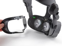
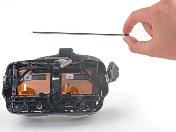
1. adıma gitFollow this guide to replace one or both eye tubes on a Valve Index VR headset.
Power off and unplug your Index before you begin your repair.
Note: this is a cumbersome repair with small, loose components that may fall out during the process. Work slow, and carefully keep track of any pieces that fall out.
Neye ihtiyacın var
Tamir Setleri
Bu kitler, bu kılavuzu tamamlamak için gereken tüm parçaları ve araçları içerir.


Parçalar


Aletler


Daha fazlasını göster…
-
-
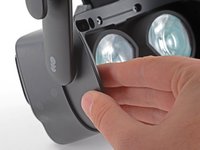
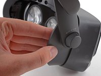
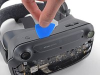
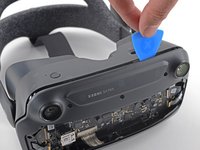
Twist the eye tube relief knob clockwise to fully extend it.
-
-
-
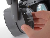
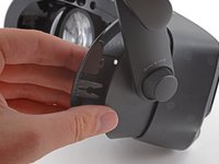
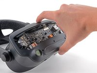
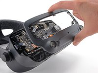
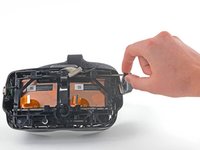
Use your hand to gently pull the face gasket straight off of the headset.
-
-
-
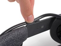
Insert the flat end of a spudger in between the bottom of the head strap clip and the head strap padding.
-
Pry up on the head strap clip until it is unclipped from the head strap.
I didn't really see the need to unclip this or do the next step so I skipped it. It seems easy enough to unplug the cable while it's still attached to these, so unless you're really concerned about the cable bending a little more than it already does it seems unnecessary.
-
-
-
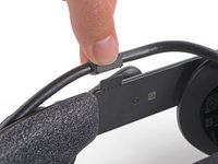
Use your fingers to pull the tether cable straight up off of the head strap cable guide.
-
-
-
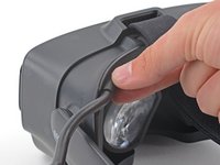
Use a T5 Torx screwdriver to remove the four 6.0 mm screws securing the face gasket bezel to the headset.
-
-
-
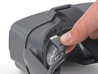
Grab the left edge of the face gasket bezel with your hand and slide it off of the headset.
-
-
Bu adımda kullanılan alet:Tweezers$4.99
-
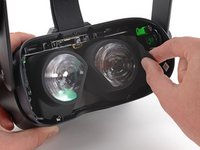
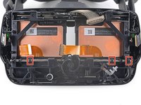
Use a pair of tweezers to separate the left edge of the eye tube gasket from the headset.
-
Repeat the process for the right edge of the gasket.
-
-
-
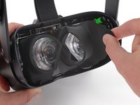
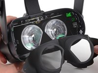
Gently peel the eye tube gasket out of the headset.
my headset has an additional piece of plastic that yours doesnt have, and its not letting me remove the lenses in later steps
I was pleased to discover that the adhesive on the rubber gasket stays sticky enough to stay in place after reassembly (at least so far) so you may not need to worry about reapplying new glue.
-
-
-
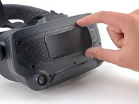
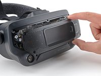
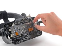
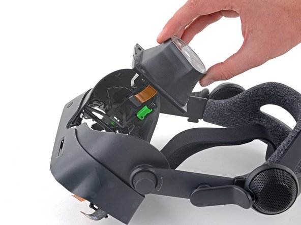
Use your hand to pull the front cover straight off of the front of the headset.
Whoever wrote this is a moron.
-
-
-
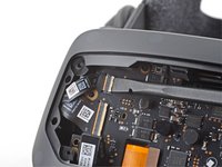
Use a T5 Torx screwdriver to remove the four 5.4 mm screws securing the motherboard cover to the headset.
-
-
-
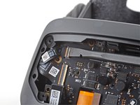
Use a T5 Torx screwdriver to remove the following eight screws from the front fascia:
-
Four 6.3 mm screws with fine threads
-
Four 6.0 mm screws with coarse threads
-
-
-
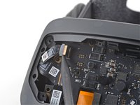
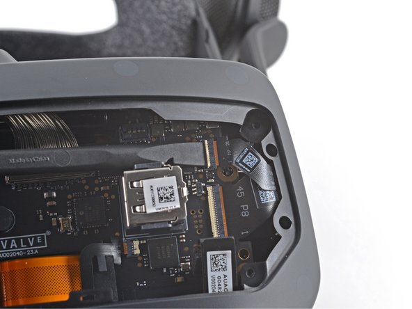
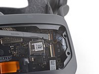
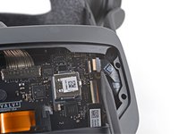
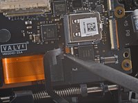
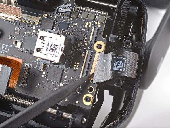
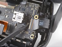
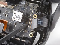
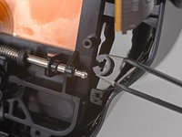
Use a spudger to unlock the ZIF connector at the top-left corner of the motherboard.
-
Disconnect the FPC ribbon cable from the motherboard.
-
-
-
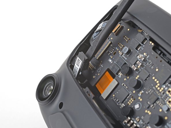
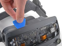
Insert an opening pick in between the front fascia and the headset.
-
Slide the opening pick over to separate the front fascia from the headset.
there are adhesive strips at the 11:30, 01:30, 05:30, and 06:30 positions. Slow, gentle prying removes the front fascia. There are no clips holding it in place.
-
-
-
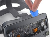
Continue sliding the opening pick along the perimeter of the front fascia until all edges are free.
Frontblende ist sowohl oben als auch unten an zwei Stellen leicht eingeklebt.
Falls die Frontblende bei Schritt 21 nicht abgeht, könnte der Klebstoff dafür verantwortlich sein.
In dem Fall kann man ihn mit dem Plektrum von der Blende lösen.
-
-
-
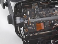
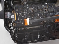
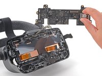
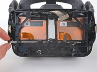
Note the seven cables that must be disconnected in the following steps before the motherboard can be removed.
note that the wheel that adjusts the distance between the eyes goes over the boar. So you will tuck the board under it.
-
-
-
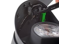
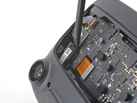
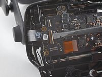
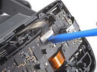
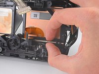
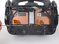
Use your finger or an opening tool to unlock the display cable connector at the top of the motherboard.
-
Carefully disconnect the display cable connector.
this one is pretty difficult, and could use some more explanation (esp since the teardown video of the index skips it completely). you need to lift up on the corner of the cover, and then use the pointy end of the spudger to slowly wiggle the cable UP and out of the connector, a little at a time on each side.
Good tip, this is not a press connector. Once the cover is swung open it slides out upwards not away from the board
-
-
-
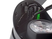
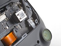
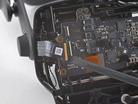
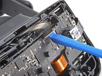
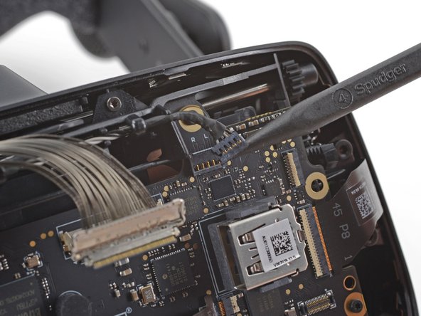
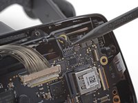
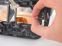
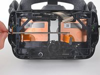
Use the pointed end of a spudger to gently disconnect the bundled cable connector from the top-right corner of the motherboard.
don't push up on the indented plastic
-
-
-
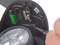
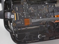
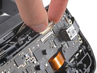
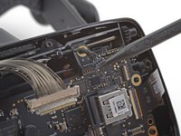
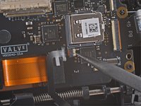
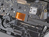
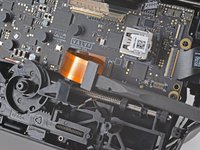
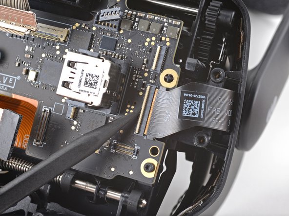
Use the pointed end of a spudger to unlock the ZIF connector next to the USB port on the motherboard.
-
Disconnect the FPC cable from the motherboard.
Not sure if this is on every headset, but mine had adhesive holding this cable to the motherboard and to the press connector cable. Be very careful peeling these apart, the adhesive is a little strong. Using the guitar-pick looking thing from the fix kit managed to separate them for me, but it might have been sheer luck lol.
-
-
-
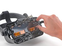
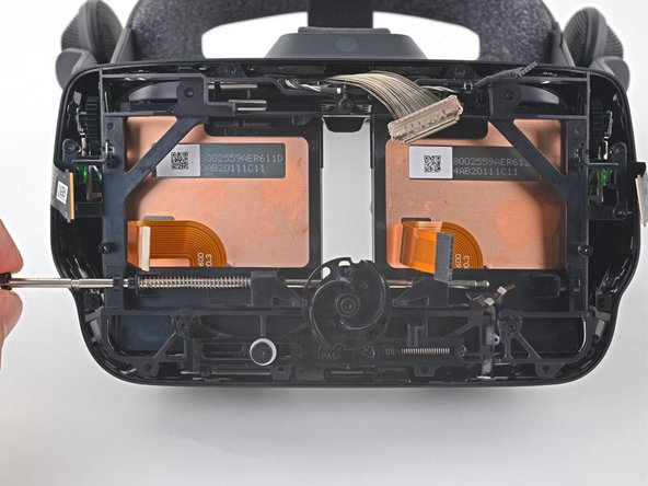
Use a T5 Torx screwdriver to remove the five 6.0 mm screws securing the motherboard to the headset.
-
-
-
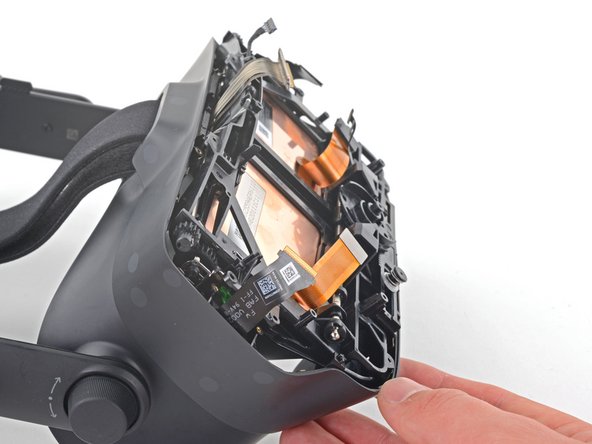
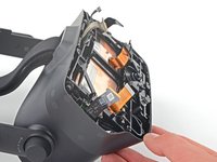
Grab the motherboard by the USB port and carefully remove it from the headset.
During reassembly be sure to align the ipd slider with the gap on the back of the right eye tube. The ipd adjustment slider is located on the top left of the motherboard and is very easy to miss.
Failing to align that the motherboard and the eyetube will result in resistance while adjusting the ipd, as well as an incorrect ipd being used in steamVR (which doesn't feel too great).
-
-
-
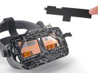
Lift the motherboard shield off of the two cross-shaped alignment pegs.
-
-
Bu adımda kullanılan alet:Tweezers$4.99
-
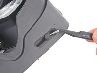
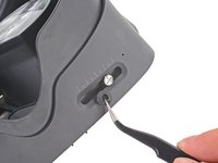
Use your tweezers to remove the rubber boot covering the IPD adjustment screw.
On reassembly, the best method for getting this back on is to get one end on and pulling until it's about half on. Then begin pulling with tweezers and spinning at the same time.
if you're struggling to get this back on, I'd recommend prying at the underside (specifically at the part with the little dent on it) with your flathead screwdriver bit until it splits, then pulling it on and over, using your screwdriver to fold the two halves of the rubber over the screw.
The way I managed to get this back on was to slide the adjuster all the way to one side (eg all the way right) and then put it on starting on the left, then I was able to use the pointy end of a spudger coming in from the front or back of the headset to slide in between the screw head and the rubber piece, into the pocket of the rubber piece (where it folds over) and stretch that part over the sides. The final side I was able to slowly get on just by rubbing the top of the rubber piece in that direction with my fingernail until it went on fully. It definitely took some time.
-
-
-
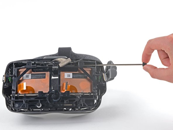
Use a T5 Torx screwdriver to remove the five 4.5 mm screws securing the midframe.
These are fine threaded screws, in case you get your screws mixed up. They are also defined by the only set of 5 with blue locktite on them.
-
-
-
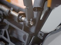
Remove the left end gear from the eye tube rail.
Be careful, there are retainers and plastic bushings on the outer sides of the rail, just inside of the midframe. I removed these with tweezers as I slid out the rail. To reinstall, I had to feed the retainer through the little hole in the front of the midframe and work it into place with the tweezers. I got the final positioning with the pointy end of a spudger. You can see one of the retainers in this picture, just to the right of the inside of the midframe where the rail is sticking through. The hole to feed it through is just below it, where the last bend of the retainer is sticking out.
-
-
-
Grab the gear on the opposite side and slide the eye tube rail out of the headset.
I had two small black pieces that look like they belong on the eye rail pop off on this step. https://imgur.com/a/tZ1mxPf Anyone have any idea where they go back on during re-assembly?
I had this problem too. If you look at the below disassembly picture you can see that these are bushings on the inner side of the gear axel. This is extremely easy to miss. They face opposite sides and are on either side of the axel, there is also a spring on the inside of these that is completely neglected in this guide.
These bushings are used to ensure that the FOV adjustment axel gears remain flush.
Xayrga -
Wish i had read the comments here. Both the little metal bar and plastic piece went flying on both sides when I removed the rod. Took me a good hour to find one that fell. Honestly the hardest part of reassembling this for me was getting that little piece back how it's supposed to be on both sides.
Did you have just one metal bar or two? Could have sworn two popped out but now I can only find one. Did you happen to snag a picture?
Reassembling in this step is one of the most difficult things I've ever had to do. I've been at it for days and haven't been able to fit in back in place.
I lost one of the two springs/wires when removing the rod - I'm warning anyone to BE READY with the magnet screwdriver or when you start pulling it out- the springs are very thin and will slip in to the tiniest gaps in the headset. When trying to reassemble, I keep dropping it into little gaps and struggle to get itback.
I think the first one I lost might be within the old eye tube - going to try cracking it open to get it back.
There really needs to be some more direction in this guide here other than 'align the springs.' this has been an ordeal, kudos to anyone with the dexterity to pull this off.Joj -
I'm convinced everything in this guide is ambigious and the person who wrote it never even touched a headset.
To answer my own question. Yes there is a set of bushing and spring on each side. The spring here is a bent piece of metal, with some bends in it. The side with the larger bend goes into a small hole at the bottom and is used for retention. If you thread the top through the hole and kinda get it in there straight you will see how it lines up. This is a pretty big step for iFixit to miss. It is a pain to get in so if you are reading this beforehand use some tape or tac to stick the side coming through the hole in the plastic frame down. Much easier to get it all in that way.
Any easy way of getting those springs back in cuz &&^& me I can't get em
Ok, I figured out a workaround if you're having trouble getting those stupid little wires clipped through the hole and onto the bushing.
I figured this was like trying to shove a ship into a bottle rather than building a ship in a bottle. So I ditched the wires, got a spool of wire of similar width, then just fed it through the hole and bent it around the axle, bent it into place back in the hole, and clipped it for length. Still very difficult, but doable.
Got the headset together, and haven't had a problem adjusting the knob, so I think I did well here.Found a way to do it, step by step:
0. Make sure the plastic bushing is oriented the right way, as in the picture.⏎⏎
1. Fit the rod into the headset from the right side.⏎⏎
2. Use the tweezers to put the bushing on. Push the rod only as to fit and mount the bushing.⏎⏎
3. Fit the spring the bent side-first into the hole. Beware, it might fall into the inside of the headset. Orienting the headset diagonally helps. ⏎
4. Guide the spring with tweezers to mount it on the rod.5. !!! Guide the rod through the holes in the eye tubes. !!!
6. Stretch the spring and the bushing diagonally. Push the bushing slightly to the center of the headset while you lift the spring slightly with the tweezers. The spring has to fit inside the bushing.
7. Align the parts as in the picture/
DO NOT PUSH the parts completely to the side, the spring WILL fall out and you will contemplate your life choices.For the left side, reverse steps 2 and 3: The spring needs to come in first.
I'll try to add this to the repair guide.
Make sure the FOV distance is same on both sides of the headset when reassembly the cogwheel. I missed this and needed to backtrack to this step and resync the sides. You just need to remove the cogwheel on one side so the sides can move independly of eachother, now make sure the sides sync and reistall the cogwheel.
So the way I approached the rails and the bushing with the spring was to use the thinnest spudger I had (basically just a metal rod) to follow the rail as I pull it out so that the bushing and spring slide onto the new rod. I was able to avoid having to re-insert either spring since that sounds very difficult. I also ended up doing 1 side at a time, pulling the rods halfway out to one side so that I only have to worry about keeping 1 spudger in place at a time. I figured if I tried to do both with 2 metal rods holding both springs in place I would surely knock one out and lose the spring. I also followed the first spudger with a second spudger going back the other direction (from center through the hole towards the outside) so that I could only capture the spring and not the bushing. It seemed more stable that way and less likely the spring will slip. You could also temporarily tape the spudger to the frame to keep it secure holding back the spring while you work.
-
-
-
Use a spudger or your fingers to remove three of the four clips from the lower eye tube rail.
-
-
-
Hold each spring with one hand to prevent them from ejecting as you slide the lower eye tube rail out.
-
-
-
Remove the lower eye tube rail.
If you're like me and had the swirly gear piece thing in the middle fall out, make sure you put it back in correctly or your IPD adjustment will be wrong. You can use the picture in the guide as reference for the position of that piece vs the position of the IPD slider. Move the slider at the bottom left screw with white washer thing to the same position as in the guide, and drop the swirly gear in the exact position as shown in this guide.
Alternatively, you can push the IPD mechanism into the lowest IPD (closest together) setting and set the swirly gear thing in the position where both of the little half circle "notches" in it are perfectly horizontal / at the same level on each side.
Mine popped off. How do you know it's in the correct position? My adjuster can reach both ends and steamvr reports 58 and 70mm is that good enough verification?
-
-
-
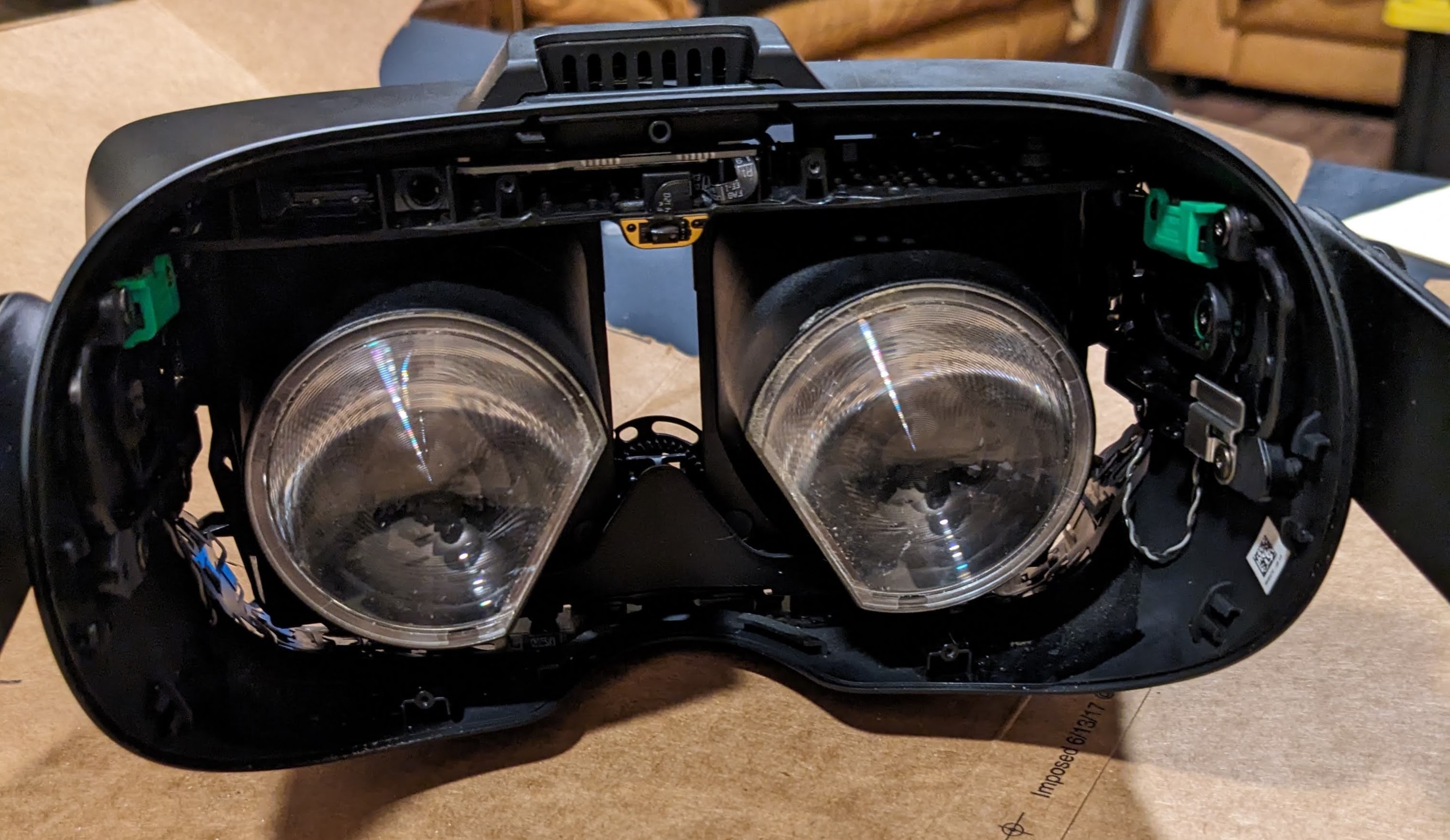
Remove the eye tube(s).
The reconstruction steps should be included as well...
Installation is opposite of removal
Wasn't exactly opposite, those springs did not want to go back in!
Fizz -
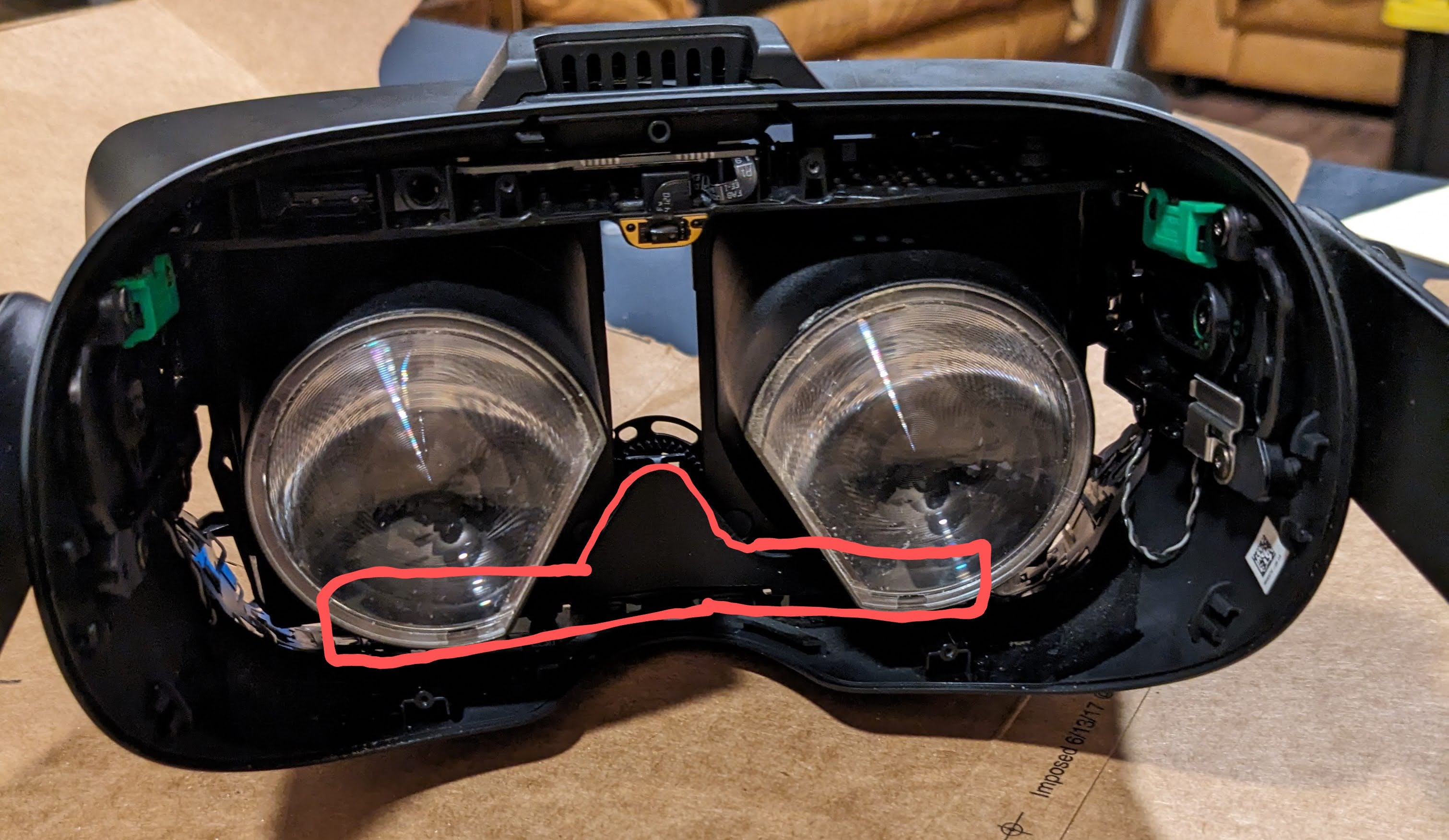
I can't seem to lift the eye tube out, there is this plastic part in the front that blocks it (they are loose but there is no position in which they can be removed):
I also have that plastic part. it is glued to the inner plastic frame. So I left it alone just folded it out of the way so that eyetube could be pulled out ( bottom side first)
Pouya -
I have that part too. I was able to get the eyepieces out by tilting them back, and then flexing the top of the index to let them slide underneath it. Make sure that your eye relief adjustment is as far out and thus as loose as you can make it.
Can't remove the lenses either, the plastic frame is not giving enough space to pull them out. There is no way you can remove or bend the plastic frame holding the eyetubes together without breaking it, either.
There should have been extra steps provided to remove that thing.Apparently you're supposed to bend the upper frame slightly so as to give the screw holes on the eye tubes some space to exit.
Contrary to what the author says, no, it won't break. It's a firm plastic.
There has been a snap sound but this is the step that does require some force to complete.Yep, also had this nosepiece-shaped piece of plastic making removing it impossible. The thing isn't present in the teardown video, so might be a different version?
I ended up slightly flexing the piece to free the eye tube, but I heard something snap, and then I was able to wiggle it around a little more, making installing new tube easy. . Haven't completed the operation, hopefully I didn't screw myself here.The hard plastic nose piece in between the lenses can be removed with light to light medium pressure there are three clips similar to the clips holding the inner facia piece on.
once removed, the tubes come out with ease.
-


Compare your new replacement part to the original part—you may need to transfer remaining components or remove adhesive backings from the new part before installing.
To reassemble your device, follow the above steps in reverse order.
Take your e-waste to an R2 or e-Stewards certified recycler.
Repair didn’t go as planned? Try some basic troubleshooting, or ask our Valve Index Answers community for help.
İptal et: Bu kılavuzu tamamlamadım.
21 farklı kişi bu kılavuzu tamamladı.

20 Yorum
I gained two extra small pieces not mentioned, I think when removing the top rail, they just dropped out into the housing. Looks like they go next to the eye tubes and are not included with the replacement so make sure you don't lose them!
I believe those are suppose to add tension to the top rail. I lost mine but it should be for a small metal spring tensioner (I think).
Gabe -
Hey, you guys forgot to mention anything about 2small pieces of bent metal no thicker then a staple that looks pretty important. Might want to include every piece that may be affected when assembling/disassembling the headset, Especially in the later stages.
wtf are these??? I also had them fall out and don't know what they are!
I know this is a little bit late, but I'm just going to post this here for anyone doing this in the future: They mention this in step 39. They are EXTREMELY hard to get back in. I recommend putting the headset on it's head and then using your fingers, not tweezers, dropping them in the small upper hole (lower from the index's view). I took a photo of it here.
The metal clip holds the plastic tube in place that the upper rail goes through.
My IPD adjustment is way out of whack now after a left lens replacement. It's reading much higher numbers than actual and the lowest possible setting reads at 63 or so. Anyone else have their IPD adjustment go off? Any ideas on how to fix it?
For reference I figured this out with help from a comment at the motherboard stage. There is a tiny slider at the top left of the motherboard that fits into a slot on the rear of the RIGHT eye tube (the left eye tube when looking from the motherboard side). When that slide is properly in its slot the digital IPD lines up with the physical IPD correctly. I had missed it when doing a left eye tube replacement because I hadn't focused on the other side.
Jeremy P -
I added a comment on step 21 that shows a picture of this, in case anyone is having the same problem.
For anyone looking, the picture schweinsfuss posted is on slide 21. it's hard to see but the non-rubber component needs to be between the two rubber pieces for it to be correct.
wear it. see what eye tube is faulty. play a game.
Did it and thanks to this guide the Index is working again.
For everyone searching the web: My symptoms were vertical white lines in my left eye. Got the new eye tube from iFixit and everything is working now!
The Guide needs two updates though.
Step 39 needs to show the black pieces and springs for reassembly as this was very hard. (I think one of the parts is missing in thge pictures of the guide ;-) )
And There seems do be a newer version of the headset that has a plastic plate over the bottom parts of the tubes that prevent them from being extracted. This part is missing in this guide.
BIG THX @samomio for the guide and iFixit for having the part!
I had the same experience with the plastic part. Just bend it down. It just seems to be some kind of dirt-guard. It is quite bendy and doesn't snap or anything. I went pretty rough on it to get the tubes out.
I sold my Index on eBay and somehow during shipment black bits of old foam or something fell out and were visible in the screen so I had to give him a refund. I took the lenses out from the front. I heated them up carefully with a heat gun and used a suction puller and a steel spudger but I slipped and scratched one lens They came out (just one side) seperated. I cleaned all the gunk out and reassembled it. Two years ago - still using it every day. the scratch which is quite clearly visible is not really visible close up strangely enough so it doesnt interrupt my gaming. Now that I have removed a lens I am comfortable that I could easily remove an Index lens. (ratcat17@hotmail.com)
Extremly good guide, took me 2 hours in total. My tip is to print out all the pages, lay them out as you go and put cups or something as containers for the parts on the specific step. There are a huge number of tiny parts in this thing. Makes it way easier to reassemble. Also read step 39 carefully! During reassembly make sure that the upper rail actually goes through the small plastic tube on the eye-tubes, otherwise you won't be able to adjust IPD.
Awesome guide.
Should be mentioned that when turning the headset upside down to remove the eye tubes themself that the gear thing in the middle will fall out, and is a little tedious to get into the right orientation when reassembling.
Also the paperclip-type "springs" are extremely difficult to get back in, would be nice to have more thorough installation instructions on that.
I ended up threading it back through the hole at the bottom, and using tweezers to pull it back up and over the plastic bushings.
Reinstalling the tiny little springs was a nightmare, but I got it done. I found it easiest to turn the headset upside down so that gravity would hold the spring in the right orientation. The rest was patience, dexterity, and a lot of luck...