
Google Pixel 7a Wireless Charging Assembly Replacement

Giriş
1. adıma gitThis repair guide was authored by the iFixit staff and hasn’t been endorsed by Google. Learn more about our repair guides here.
Follow this guide to replace the wireless charging assembly in your Google Pixel 7a.
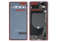
The wireless charging assembly, also known as the inner housing, consists of the logic board cover and wireless charging coil.
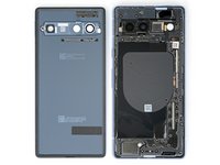
Note: The Verizon model Google Pixel 7a (G0DZQ) has a 5G mmWave antenna. If you have this model, some photos in this guide differ, but the procedure is the same.
If your battery is swollen, take appropriate precautions.
You'll need replacement adhesive in order to complete this repair.
Note: Any repair can compromise the water resistance of your phone. Retaining water resistance after the repair will depend on how well you reapply the adhesive.
Neye ihtiyacın var
Parçalar


Aletler


Daha fazlasını göster…
-
-
Unplug any cables from your phone and fully power it down.
-
-
-
Apply a heated iOpener to the bottom edge of the rear cover for three minutes.
If you have an IR Thermometer or Thermal Camera, you're going for 85C/185F. Even with mini heat guns, this comes up fast; just a few seconds of heat.
-
-
Bu adımda kullanılan alet:Clampy - Anti-Clamp$24.95
-
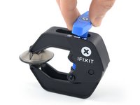
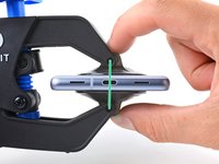
Pull the blue handle backward to unlock the Anti-Clamp's arms.
-
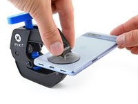
Slide the arms over the bottom edge of the phone, with one suction cup on the rear cover and one on the screen.
-
Squeeze the cups together to create suction.
-
-
-
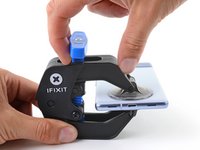
Pull the blue handle forward to lock the arms.
-
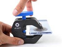
Turn the handle clockwise one full turn (360 degrees), or until the suction cups begin to stretch.
-
As the cups stretch, make sure they stay aligned with each other. If they keep slipping, remove the Anti-Clamp and apply tape for the cups to stick to.
-
-
-
Place an object under your phone so it rests level while between the Anti-Clamp's arms.
-
Wait one minute, or until the adhesive separates, for a gap to form along the bottom edge of the phone.
-
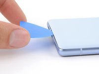
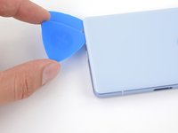
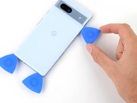
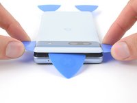
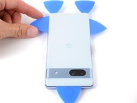
Insert an opening pick into the gap between the rear cover and the frame.
-
Remove the suction cups from the phone using their pull-tabs and set the Anti-Clamp aside.
-
-
-
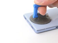
Apply a suction handle to the center of the bottom edge of the rear cover.
-
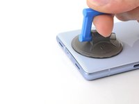
Pull up on the suction handle with a strong, steady force until a gap forms between the rear cover and frame.
-
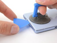
Insert the tip of an opening pick into the gap.
-
Remove the suction handle.
-
-
-
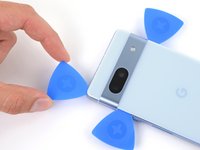
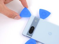
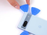
The rear cover is secured with adhesive around the perimeter of the frame and near the cameras. Use this picture as a reference while you slice the adhesive.
There is also a plastic bezel attached to the rear cover which you DO NOT want to remove. It's a very similar (temperature wise) adhesive that connects that bezel to the cover, as connects the bezel & cover to the frame, but since only the frame side adhesive is provided in the kit, you want to try not removing that bezel from the rear cover.
-
-
-
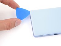
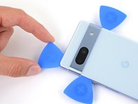
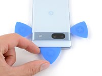
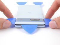
Angle the opening pick upward so the tip faces away from the frame.
-
Slide your pick to the bottom left corner of the rear cover.
-
Leave this pick in place to prevent the adhesive from resealing.
-
-
-
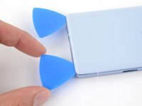
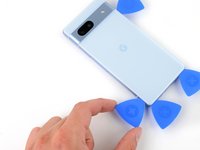
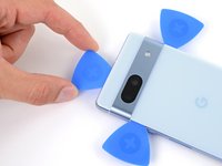
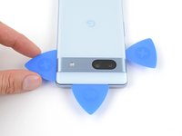
Insert a second opening pick in the bottom left corner.
-
Slide the new pick to the bottom right corner of the rear cover to separate the bottom edge adhesive.
-
Leave this pick in place to prevent the adhesive from resealing.
-
-
-
Apply a heated iOpener to the right edge of the rear cover for two minutes.
-
-
-
-
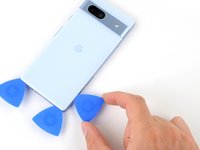
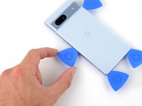
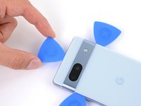
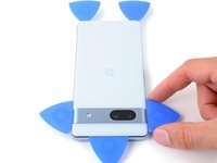
Insert a third opening pick in the bottom right corner of the rear cover.
-
Slide your pick up the right edge of the rear cover to separate its adhesive. Stop when you reach the camera bar.
-
Leave this pick in place to prevent the adhesive from resealing.
-
-
-
Apply a heated iOpener to the left edge of the rear cover for two minutes.
-
-
-
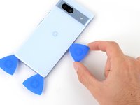
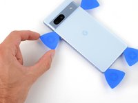
Insert a fourth opening pick in the bottom left corner of the rear cover.
-
Slide your pick up the left edge of the rear cover to separate the adhesive. Stop when you reach the camera bar.
-
Leave this pick in place to prevent the adhesive from resealing.
-
-
-
Apply a heated iOpener to the top edge of the rear cover for two minutes.
-
-
-
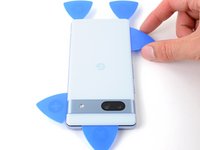
Insert a fifth opening pick in the top left corner of the rear cover between 8 mm and 10 mm (0.3–0.4 in) deep, or just over halfway between the tip of the pick and the iFixit logo.
-
Slide your pick halfway across the top edge to separate the antenna bracket adhesive. Stop at the halfway point along the top edge.
This is the trickiest part, because the camera bar wants to keep the back cover from lifting. It's like a break in the leverage, of the lower part of the case. Go easy.
-
-
-
Pull your opening pick out to a depth of 3 mm.
-
Slide your pick to the top right corner to slice the rest of the top edge adhesive.
-
-
-
Roll the top edge pick so its flat edge is under the rear cover.
-
Roll the picks on each side of the camera bar so their flat edges are under the camera bar.
-
-
-
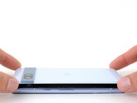
Use the opening picks under the camera bar to pry the top edge of the rear cover from the frame.
-
Pry back and forth until the camera bar loosens.
-
-
-
Slide the opening picks from the camera bar down the long edges of the rear cover to separate any adhesive that may have resealed.
-
-
-
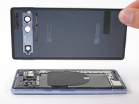
Remove the rear cover.
-
Now is a good time to test your phone before sealing it up. Power it on and check that it works. Power it back down before you continue reassembly.
-
Follow this guide to apply new adhesive and install your rear cover.
This reassembly link, "Follow This Guide" is really important. It's a shame they did it this way, but make a note of it for when you come back through.
-
-
-
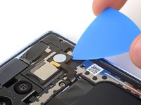
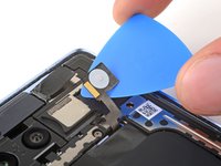
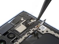
Apply a heated iOpener to the flash unit for one minute to soften the adhesive securing it to the logic board cover.
-
-
-
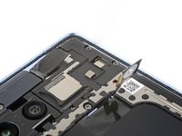
Slide your pick under the right edge of the flash to separate the adhesive securing it to the cover.
Cuidado en este procedimiento, algo dañe y el flash quedo en color azul.
-
-
Bu adımda kullanılan alet:Tweezers$4.99
-
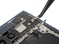
If the copper tape lifted away with the flash, use tweezers or your fingers to remove the black foam residue from the logic board cover.
-
-
-
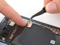
Apply a heated iOpener to the underside of the flash for one minute.
-
Hold the neck of the flash cable steady and use tweezers to peel and remove the copper tape from the flash unit.
It can be a little tricky applying the new copper tape. I was able to get through it by:
- Pressing down the black adhesive on the logic board cover,
- Lining up the new copper with the flash's backside,
- Sandwiching them both when pressing the flash back into place.
Did not find the new copper tape in my kit, and this was really confusing. Would be helpful to show the part, from the kit here.
-
-
 Bu adımda kullanılan alet:iFixit Precision 4 mm Screwdriver Bit$2.99
-
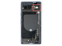
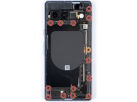
Use a 3IP Torx Plus driver to remove the thirteen 4.3 mm screws securing the logic board cover.
-
Use a 1IP Torx Plus driver to remove the 1.5 mm screw securing the right edge of the cover.
The T2 Torx driver that came with the tool kit does not fit. It seems a bit too large. Is this really T2 Torx?
This is right. This is because the Pixel 7a uses Torx Plus screws, which are less commonly available than regular Torx bits. We're only able to provide regular Torx bits in our kits, for now. So, the bit size is slightly different to reduce the likelihood of stripping your screws out. When using the T2 bit to remove Torx Plus 1IP screws, use constant downward force to keep the bit fitting as well as possible.
結論から言うと、おそらくネジの専門家でも現物を見ないと判断できないので、長さ1.5mmのM1ネジを入手できるお店をご存知ならネジの現物を持っていって判断してもらうのが間違いないです。そのようなお店をご存知なくて、元々のネジが再利用できそうなら、再利用するのが正解だと思います。
私はPixel 7aの実機を持っていないのでネジ頭の種類は画像で判断するしかないのですが、おそらく低頭ネジ(pancake head、締め付け面が平ら)か皿ネジ(flat head、締め付け面が円錐形)かと思われます。トルクスプラスの1IPネジを作っているメーカーのサイズ表を見てみましたが、低頭ネジについては太さの情報がありませんでした。皿ネジについてはM0.9とM1の2種類の記載がありました。
仮にこの2種類のどちらかであるとしても、どちらかを判別するには専用の道具が必要になりますし、別のサイズの特注品の可能性もあります。また、自力で判別できたとしてもこのサイズのネジを扱っているのはネジの専門店だけだと思われますので、結局ネジの専門店に現物を持ち込んで相談するのが最適解になるかと思います。
なお、トルクスプラスIPネジと普通のトルクスネジではネジ頭の溝形状が異なるので、トルクスプラスIPネジを通常のトルクスドライバーで扱おうとすると隙間ができるはずです。そもそも強い締め付け力が必要な場所でもなさそうですし、ネジの締め付けや取り外しに問題ない程度の舐め具合であれば、元々のネジを再利用するのが現実的ではないかと思います。
なお、私はネジの専門家ではないですしPixel 7aの実機を持っているわけでもありませんので、上記の内容に問題がある可能性があることはご了承ください。また、不備を見つけた方がいらっしゃいましたら訂正していただければ幸いです。
最後に参考資料として、トルクスプラスネジの寸法規格表を紹介しておきます。どちらも英語です。
ポップリベット・ファスナー社のトルクスプラスねじパンフレット(PDF)(サイズ表は14ページ)
Servause -
It is unbelievably disingenuous to claim that the T2 Torx bit you supply fits the 1IP Torx Plus Screws. I'm sitting here with my phone half-dissembled searching Amazon to see if I can find a T1 Torx bit or a Torx Plus bit that can be delivered today. Hopefully anyone who reads this guide before buying, opens these comments and decides you aren't worth their time. I also plan to leave a review on the kit itself. I can't believe I paid $10 in shipping and waited a full week for this half-assed kit.
This si a scam, don't waste your money on this. They make you buy a hole set of tools even when the know the don't have the proper tools to get the work done! That T2 Torx IFIXIT is selling doesn't work.
Agree with previous comments. Included T2 bit does not even come close to fitting in the torx plus 1ip screw. Having to overnight a T1 bit in hopes it works.
After overnighting a precision bit set, it now appears that the T2 bit included in the iFixit kit may be out of spec. The T2 bit from the Amazon bit set fit as described and allowed me to complete the fix.
Aaron -
Got this far just to realize the same as above. The t2 bit that comes with the kit is wayyy to large to fit this screw
Also chiming in here to advise that the T2 bit supplied is too large...hopefully this gets addressed!
This is a complete rip off to advertise a one stop shop kit and then knowingly include the wrong bit, which doesn't fit the phone. What a terrible experience. I've got a disassembled phone and now have to wait to order the proper bit. Never using ifixit again. Terrible experience.
I have a half disassembled phone that I can't take to work because of this t2 issue. Do not recommend
Read through the guide before buying the kit, but I wish I had read the comments. As mentioned by everyone else, they literally do not provide the proper tools in the battery replacement kit...
My kit came with a 1lP bit in the battery package, so was able to complete the battery replacement no issues.
Mine was the same.
This needs to get fixed. Same issue as everyone else. Disassembled phone, now unable to fix it due to wrong bits included. Not very happy with ifixit.
-
-
-
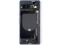
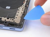
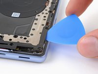
Insert an opening pick between the bottom right corner of the logic board cover and the frame.
-
Pry up to release the clip securing the cover.
-
-
-
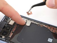
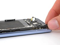
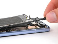
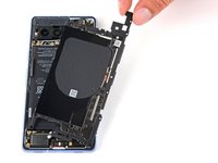
Slowly lift the top edge of the logic board cover and thread the flash unit through its cutout.
-
-
-
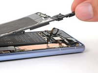
Remove the wireless charging assembly.
-


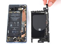
To reassemble your device, follow these instructions in reverse order.
To run a diagnostics test with the built-in Pixel Diagnostic tool, click here.
Take your e-waste to an R2 or e-Stewards certified recycler.
Repair didn’t go as planned? Try some basic troubleshooting, or ask our Answers community for help.

Ekip

If you purchased the iFixit kit, now is a good time to ensure you have all the parts: If you go to the kit page, and expand Kit Contents, you'll see the full list. The full list contains links to details on adhesive sets. These links are also in this guide document, in the upper right, in a scrollable window.⏎
⏎
Newer batteries seem to come with the 1IP Torx Plus bit taped in the tray of the battery part tray (Repair Part box). It is not in the Tools, found in the Repair Tools box (if you purchased the Fix Kit).⏎
⏎
Familiarize yourself with all the parts, including the six adhesive items. Ensure none of the components fell behind the parts tray and are left in the parts box (they are tiny adhesive tabs). The adhesive is VERY sticky. Don't remove the backing until you are ready to use, and then be prepared to lay the piece in place once ANY contact is made. Removal, even an edge, to better align an adhesive part is often not possible(!). The adhesive will stretch and bunch up.⏎
⏎
As noted at the beginning of the guide, proper installation of the adhesive is required to maintain water resistance, but also to transfer heat correctly.
Chris Romer - Yanıt